Wattstopper
®
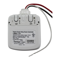
Digital Lighting Management Single Relay Room Controller
Gestion numérique de l’éclairage Contrôleur de pièce à relais unique
Control de la iluminación digital Controlador de habitación de relé simple
Quick Start Guide • Guide de démarrage rapide • Guía de inicio rápido
No: 22893 – 11/17 rev. 2
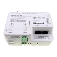
Catalog Number • Numéro de Catalogue • Número de Catálogo: LMRC-101
Country of Origin: Made in China • Pays d’origine: Fabriqué en Chine • País de origen: Hecho en China
SPECIFICATIONS
Input Voltage ....... Single Phase 120/230/240/277VAC, 50/60Hz
Load Requirements
Incandescent ........................................20A @ 120VAC
Ballast ...........................................20A @ 120/277VAC
Motor ............................................ 1Hp @ 120/240VAC
Output ....................................................... 150mA @ 24VDC
DLM Local Network Characteristics:
Provides low voltage power over Cat 5e cable (LMRJ).
Supports up to 24 communicating devices, including 4
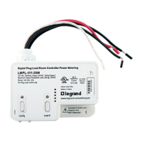
LMRC‑10x or LMPL‑101 max per each DLM Local Network.
Free topology up to 1,000ft of low voltage cable.
Environment:
Operating Temperature .........32° to 104°F (0° to 40°C)
Storage Temperature ...........23° to 176°F (‑5° to 80°C)
Relative Humidity ...............5 to 95% (non condensing)
Patent Pending
PLACEMENT EXAMPLE
This unit is pre-set for Plug n’ Go™ operation, adjustment is optional.
For full operational details, adjustment and more features of the product, see the
DLM System Installation Guide provided with Wattstopper room controllers, and also
available at www.legrand.us/wattstopper.
Installation shall be in accordance with all applicable regulations, local and NEC
codes. Wire connections shall be rated suitable for the wire size (lead and building
wiring) employed.
For Class 2 DLM devices and device wiring: To be connected to a Class 2 power
source only. Do not reclassify and install as Class 1, or Power and Lighting Wiring.
WARNING: Do not install to cover a junction box having Class 1, 3 or Power and
Lighting Circuits.
Corner Mount
Occupancy
Sensor
Switch
Ceiling Mount
Occupancy
Sensor
Room
Controller
J Box
To
Load
DLM Local Network
(low voltage, Class 2)
LMRJ cables
WARNING: TURN THE
POWER OFF AT THE CIRCUIT
BREAKER BEFORE WIRING.
CAUTION: TO CONNECT A COMPUTER TO THE
DLM LOCAL NETWORK USE THE LMCI-100. NEVER
CONNECT THE DLM LOCAL NETWORK
TO AN ETHERNET PORT – IT MAY DAMAGE
COMPUTERS AND OTHER CONNECTED EQUIPMENT.
MOUNTING THE CONTROLLER
The LMRC‑101 room controller can be mounted external to either
a 4”x 4” or 4‑11/16 x 4‑11/16 junction box, placing it in the plenum
space or mounted directly inside a 4‑11/16 x 4‑11/16 junction box.
ATTACHING CABLES
Line
Load
J-Boxes
Load
Line
Outside a 4” x 4” or
4 11/16 x 4‑11/16 box
Inside a 4 11/16 x 4‑11/16 box
Remove rubber jack covers if using all 3 RJ45 receptacles.
Leave covers in place for all unused receptacles.