Do you have a question about the LEGRAND Wattstopper DCLV2 and is the answer not in the manual?
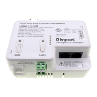
Details the 7-position wiring terminal block for the DCLV2 controller.
Explains 0-10V dimming curves and the ON/OFF option functionality.
Provides the wiring diagram for 0-10V control.
Shows the wiring diagram for ballast ON/OFF control.
Illustrates the wiring diagram for sensor input.
Instructions to enable the Auto On operating mode for the DCLV2.
Instructions to switch back to the Manual On operating mode.
Details on setting and disabling Partial On mode.
Describes the retrigger mode functionality.
Procedure for resetting the DCLV2 to its factory default settings.
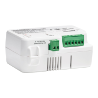
The Wattstopper Decorator Style 0-10V Controller, model DCLV2, is a wallbox controller designed for managing 0-10V dimming systems. It offers both Manual On and partial Auto On functionalities, providing flexibility in how lighting is controlled. This device is specifically engineered to work in conjunction with Wattstopper BZ Series power packs and can be integrated with occupancy sensors for enhanced automation.
The DCLV2's primary function is to control electronic ballasts and drivers for LED lighting systems. It achieves this by sinking up to 50mA, which allows it to manage up to 100 ballasts wired in parallel, assuming each ballast sources 0.5mA. The 0-10V output range of the DCLV2 operates at a minimum of 0.75VDC and a maximum of 9.5VDC, providing precise dimming control. It is a Class 2 device, receiving its operating supply voltage of 24VDC directly from an external source, specifically a Wattstopper BZ series power pack for 0-10V ballast control. The controller is also capable of receiving input from a sensor, enabling automated responses based on occupancy or vacancy.
The DCLV2 supports low-voltage DC dimming using Class 2 wires, allowing multiple circuits to utilize the same dimming signal without requiring additional power equipment. It executes a straight proportional relationship between the internal dimming level and the voltage provided, ranging from 0.6VDC to 9.5VDC.
When operating with an ON/OFF option, the DCLV2 integrates relay control. As the user ramps up the dimming level, relay 1 output switches from 0V to 24VDC, closing the power pack relay to supply line voltage to the light fixtures. Conversely, when the user ramps down and the 0-10V output reaches 0V, relay 1 switches to 0V, opening the power pack relay and removing power to the light fixtures. This allows for a smooth ramp-down of the ballast before it turns OFF. It's important to note that an ON to OFF transition may take approximately 2 seconds due to the dimming-down process, while an OFF to ON transition is immediate.
The DCLV2 offers several user-configurable operating modes to suit different preferences and applications. By default, the device is in Manual On mode, with Auto On disabled.
To enable Auto On mode:
To switch back to Manual On mode:
The DCLV2 also incorporates a Partial On mode. By default, when a sensor triggers occupancy, the DCLV2 sets the load to the dimming level it was at when Manual On or Auto On was enabled. This is referred to as Partial On. To set a fixed value for Partial On:
To disable the Partial On feature, there are two methods: Method 1:
The Retrigger Mode is another useful feature. When in Manual On mode, if a connected sensor registers a vacancy and turns the load OFF, an automatic 30-second retrigger mode is enabled. If the sensor registers occupancy during this period, the load will return to its previous level. After the 30-second retrigger period, subsequent occupancy registrations will cause the load to respond based on the Manual On or Auto On setting configured for the DCLV2.
For maintenance or troubleshooting, the DCLV2 can be reset to its factory defaults. The factory default setting for the DCLV2 is Manual On with Partial On enabled at 50%. To perform a reset:
Installation of the DCLV2 requires adherence to all applicable codes and standards to prevent personal injury or equipment damage. As a Class 2 product, it requires a low voltage cable with the appropriate number of conductors. For ease of installation, the manufacturer recommends using a deep wall box. Before installation, power to the circuit must be disconnected by turning the circuit breaker OFF. Any existing wall plate and switch should be removed. If a line voltage switch is present, the wiring must be converted to low voltage for the DCLV2, or a new wall box installed according to NEC requirements. After installing the power pack to control the lighting circuit, wires should be stripped 1/4 inch. If two wires are connected to the same terminal, they must be of the same gauge. After connecting wires as appropriate for the application, the wall plate is attached, and the circuit breaker is switched back ON.
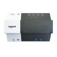
The DCLV2 is designed to be compatible with any BZ series power pack. However, specific considerations apply: the Orange, Brown, and Gray wires on the BZ-150 and BZ-250 power packs are not used and should be capped. The Manual/Auto On switch on the BZ-150 and BZ-250 should be left in the Auto-On position, as manual functionality is handled by the DCLV2. Additionally, the BZ-200 and BZ-250 must be grounded to ensure signal integrity, not for safety ground. For simple ON/OFF control systems, the 0-10V output on the DCLV2 should not be connected.
| Category | Controller |
|---|---|
| Manufacturer | LEGRAND Wattstopper |
| Model | DCLV2 |
| Voltage | 120 - 277 VAC |
| Frequency | 50/60 Hz |
| Enclosure Rating | NEMA 1 |
| Load Type | Incandescent, Halogen |