Wattstopper
®
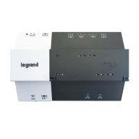
Digital Lighting Management Plug Load Controller
Installation Instructions • Instructions d’Installation • Instrucciones de Instalación
No: 24045 – 01/19 rev. 3
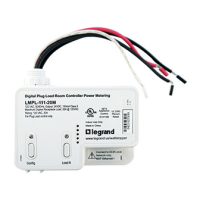
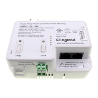
Catalog Number • Numéro de Catalogue • Número de Catálogo: LMPL-101
Country of Origin: Made in China • Pays d’origine: Fabriqué en Chine • País de origen: Hecho en China
LMPL-101-U is BAA and TAA compliant (Product produced in the U.S.)
SPECIFICATIONS
Input Voltage .............................................................................. 120VAC, 50/60Hz
Output Capacity ............................................................................150mA@24VDC
Power Supply ........................................................... Wattstopper Room Controller
Connection to the DLM Local Network .............................................. 3 RJ-45 ports
DLM Local Network characteristics when using LMRC-11x/2xx room controllers:
Low voltage power provided over Cat 5e cable (LMRJ); max current 800mA.
Supports up to 64 load addresses, 24 communicating devices including up
to 4 LMRC-10x series and/or LMPL-101 controllers.
Free topology up to 1,000’ max.
Environment ........................................................................... For Indoor Use Only
Operating Temperature ...........................................32° to 131°F (0° to 55°C)
Storage Temperature ............................................ 23° to 176°F (-5° to 80°C)
Relative Humidity .................................................5 to 95% (non condensing)
Patent Pending
This unit is pre-set for Plug n’ Go™ operation, adjustment is optional.
For full operational details, adjustment and more features of the product, see the DLM System Installation Guide provided with Wattstopper room
controllers, and also available at www.legrand.us/Wattstopper.
Installation shall be in accordance with all applicable regulations, local and NEC codes. Wire connections shall be rated suitable for the wire size
(lead and building wiring) employed.
For Class 2 DLM devices and device wiring: To be connected to a Class 2 power source only. Do not reclassify and install as Class 1, or Power and
Lighting Wiring.
PLACEMENT EXAMPLES
Switch
Ceiling Mount
Occupancy
Sensor
Plug Load
Controller
Line Voltage
(Class 1 wiring)
To Plug Load
(Class 1 wiring)
J-Box
To Other
Electrical
Outlets
Switch
Ceiling Mount
Occupancy
Sensor
Room
Controller
J-Box
Plug Load
Controller
Line Voltage
(Class 1 wiring)
To Plug Load
(Class 1 wiring)
J-Box
To Lighting
Load
(Class 1 wiring)
To Other
Electrical
Outlets
Line Voltage
(Class 1 wiring)