Group 5 Transport/Start up Page 41
Release R2.0 LEIBINGER JET3
The print head mounting should be carried out that a fast separation of the print head
from the device for cleaning purposes is possible.
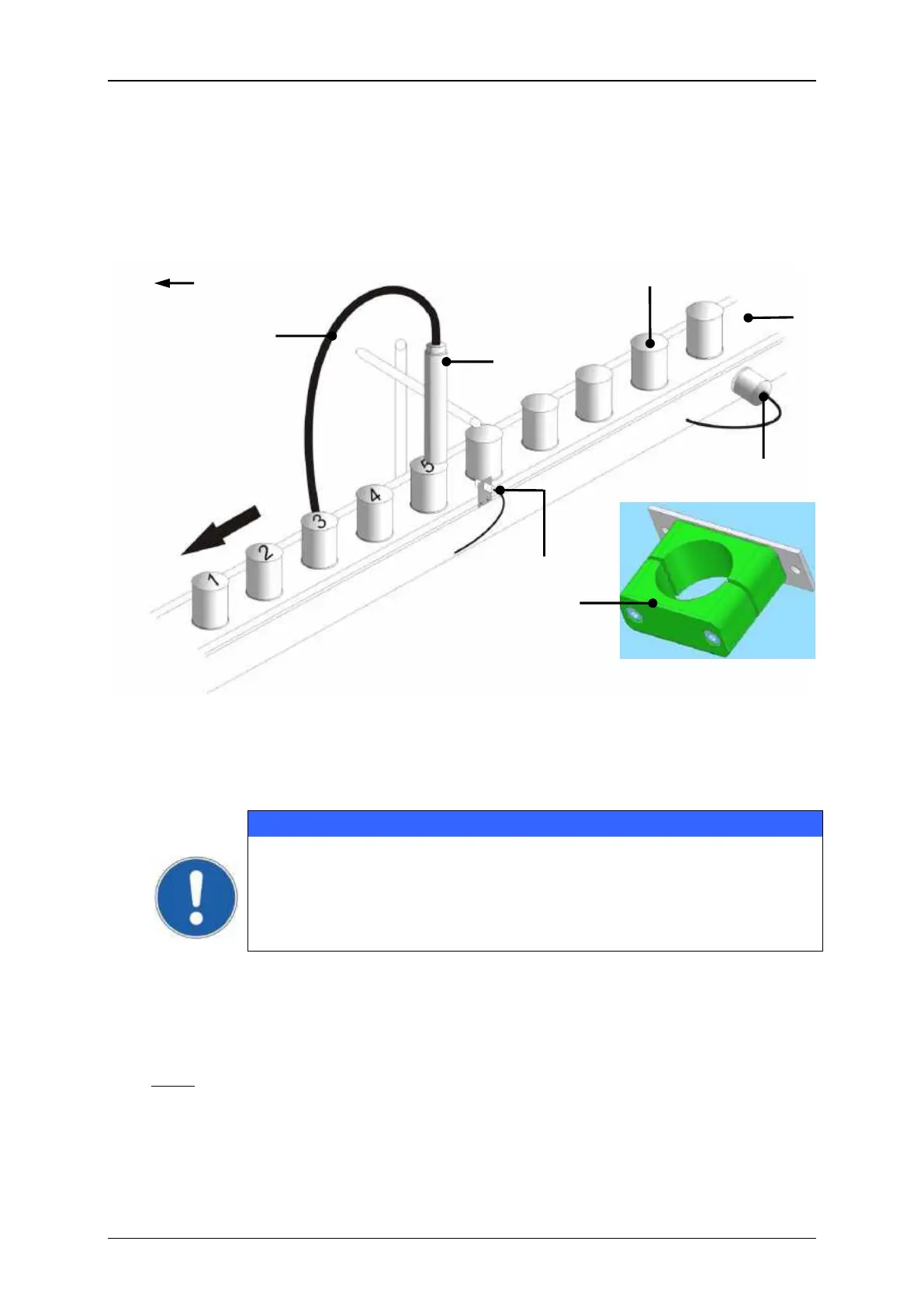
Print head installation (Example)
Print head installation (Example)
6 – Umbilical (Hose connection)
The print head should be attachted vibration-free. The hose connection
of the print head should not be smaller as a radius of R=100 mm
statistically (loop: 200 mm) and dynamically not below R=150 mm
(loop: 300 mm)!
The distance of the print head to the product depends on the required character
height. As smaller the required character height, as smaller the distance of the print
head to the product (smaller distances produce better type quality)
Note: In general a distance of round about 8-10mm is recommended.
For applications with extreme small or large character heights a micro- and macro
print head are available optionally.