Replacing modules Service manual Leica M525
04/2004 – EBTH Update 07/2007 5-2 Doc Code 10 665 751
5. Carefully swing away illuminator [Fig.3-2] downwards, over
dovetail segment.
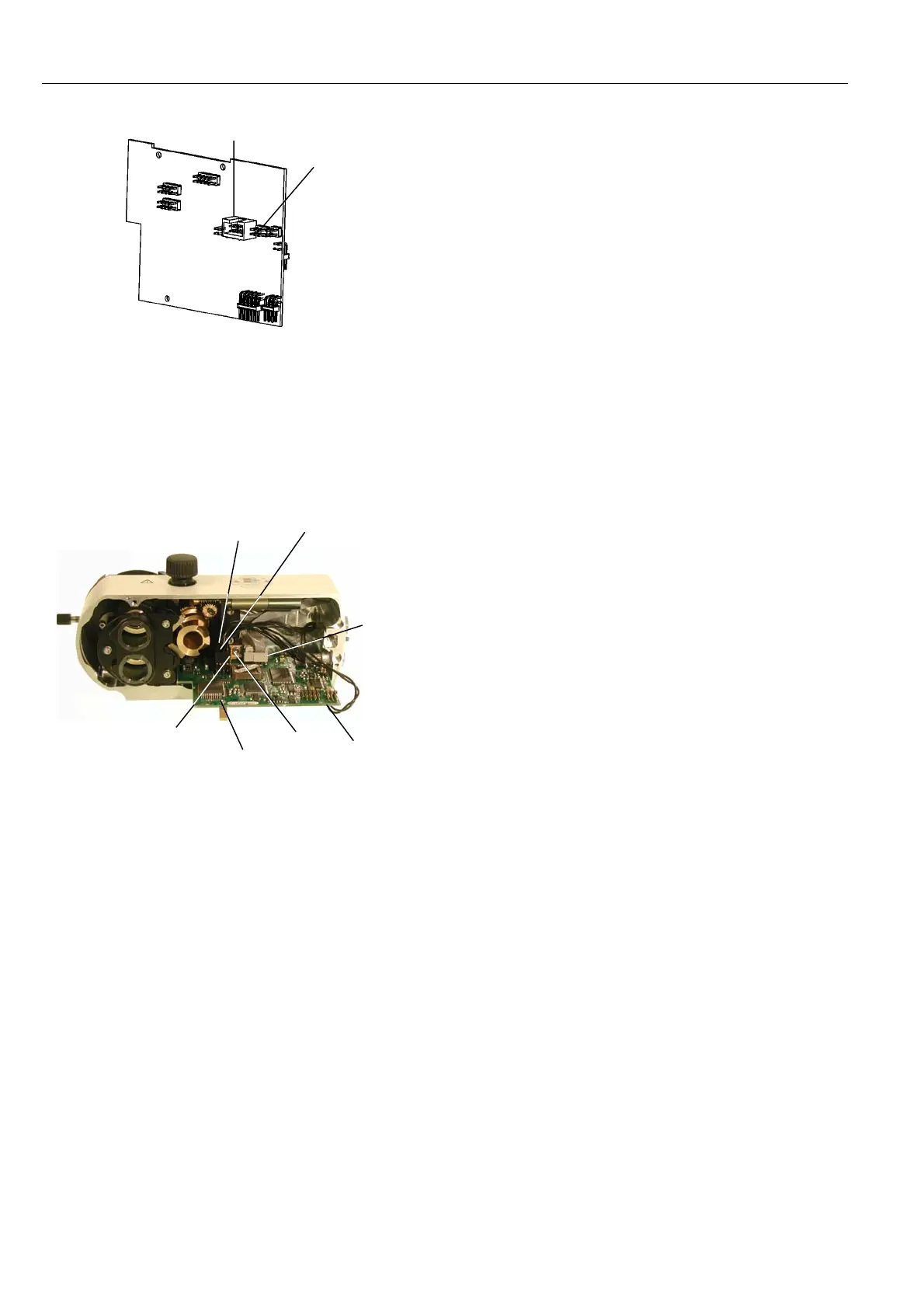
6. Pull out connectors P1, P2, P3 and P4 from motor controller
board.
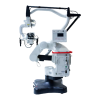
7. Remove screw [Fig.4-5] from zoom motor adapter and remove
motor controller board from zoom part [Fig.3-1].
8. Remove screw [Fig.4-6] from motor controller board positioned
and take it off.
9. Remove two screws [Fig.4-7] from motor controller board
carrier and take it off.
P 4 P 3
P 2
P 1
5
M3x6
DIN912
6
M2.5x5
DIN789
7
M2.5x5
DIN7985
Fig 4
4A. For M525 only: Carefully swing away illuminator [Fig.3-2]
Downwards, over dovetail segment until P8 and P9 become
accessible. Pull out connectors P9 and P8 from motor
controller board (Fig 3A).
Fig. 3A
P8
P9



 To Next Page