EasyManua.ls Logo

Leister LHS User Manual

Leister LHS
8 pages
To Next Page IconTo Next Page
Page #1 background imageLoading...
Page #1 background image
Leister LHS SYSTEM
Air Heater
Please read operating instructions carefully before use and
keep for further reference.
GB
OPERATING INSTRUCTIONS
The Leister Air Heater type LHS SYSTEM are suitable for building into machines,
installations or appliances and are designed for continuous operation.
Drying and heating processes of various types.
Shrinking and welding packaging films and moulded parts.
Heating conveyor ovens or heat tunnels.
Activating and loosening solvent free adhesives and melt adhesives.
Sterilizing packaging materials such as bottles, corks and containers.
Separating and fusing synthethic fibres and fabrics.
Soldering processes on thin metal parts.
Speeding up mixing processes and dissolving foams which can arise during
mixing and filling operations.
Welding thermoplastic materials.
Removing plastic mould flash.
Putting a shine on plastic surfaces.
APPLICATION
Leister Process Technologies, Riedstrasse, CH-6060 Sarnen/Switzerland
Tel. +41 41 662 74 74 Fax + 41 41 662 74 16
www.leister.com sales@leister.com
LHS SYSTEM 20S
LHS SYSTEM 20L
LHS SYSTEM 40S
LHS SYSTEM 40L
LHS SYSTEM 60S
LHS SYSTEM 60L
®

Other manuals for Leister LHS

Question and Answer IconNeed help?

Do you have a question about the Leister LHS and is the answer not in the manual?

Leister LHS Specifications

General IconGeneral
BrandLeister
ModelLHS
CategoryHeater
LanguageEnglish

Summary

Application

Safety Warnings and Precautions

Operating Instructions

Installation

Guidelines for tool installation and protection against vibration.

Air Supply Requirements

Stipulated minimum air flow and temperature limits for optimal performance and safety.

Operation Guidelines

Procedures for connecting, fitting nozzles, and proper shutdown.

Functional Protection and Tool Description

Heat Element and Tool Protection

How overheating is managed by cutting power and opening alarm contacts.

Tool Component Identification

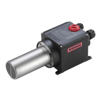
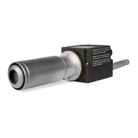
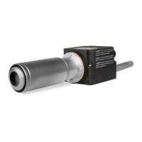
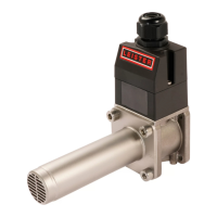
Labeled diagrams identifying key parts of the LHS SYSTEM models.

Connection and Installation - 20S/20L

Power Unit Wiring Diagram (20S/20L)

Electrical schematic for connecting the power unit for 20S/20L models.

Installation Dimensions (20S/20L)

Detailed physical dimensions for mounting the 20S/20L units.

Connection and Installation - 40S/40L

Power Unit Wiring Diagram (40S/40L)

Electrical schematic for connecting the power unit for 40S/40L models.

Installation Dimensions (40S/40L)

Detailed physical dimensions for mounting the 40S/40L units.

Connection and Installation - 60S/60L

Power Unit Wiring Diagram (60S/60L)

Electrical schematic for connecting the power unit for 60S/60L models.

Installation Dimensions (60S/60L)

Detailed physical dimensions for mounting the 60S/60L units.

Control Unit Wiring Diagram

Schematics for potentiometer and 4-20mA inputs for various models.

Training and Support

Service and Repair

Procedures and requirements for authorized service and repair.

Guarantee and Liability

Terms and conditions regarding product warranty and liability.

Related product manuals