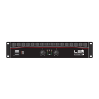
the signal is not fed to the amplifier sections) to fully open
(position 0dB - the signal is sent to the amplifier sections at the
same level as that with which it arrives at the input). In other
words, this control operates as an attenuator of the signal fed to
the amplifier.
5
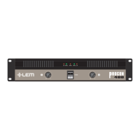
PHONES
STEREO headphone output: the AMP 2.4 has an output to
which STEREO headphones with a minimum impedance of 200W can
be connected. When the headphones are connected to this output,
the amplifiers main outputs are automatically disabled, so the input level
controls can be used as headphone volume controls.
6
AIR VENTS (AMP 4,8 & 12)
Amplifier cooling system air vents.
The fan of the AMP SERIES cooling system create a flow of air
with front-to-back direction: this means that the air is taken from
the opening on the front and, after having cooled the heat sinks
and mains transformer, is expelled through the opening on the back
side. Care must always be taken to avoid blocking these openings
and to never place the amplifier in a position which does not allow
sufficient air circulation.
7
POWER ON
ON/OFF switch with indication LED.
8
OUTPUTS
Power out: outputs to be connected to the loudspeaker enclosures.
AMP SERIES amplifiers A&B outputs both have a 4-way
SPEAKON and a BINDING-POST connectors in AMP 4,8 &
12 models and a JACK in the AMP 2.4.
Only loudspeaker enclosures (or loudspeaker enclosure systems)
within the amplifiers declared power and impedance load range
should be connected to the amplifiers outputs (see ê Technical
specifications).
Use
only speaker cables (two-core cables, normally with a red and a black
wire): do
not use screened or signal cables (cables normally used for
microphones, instruments and audio equipment in general).
Functions & controls
 Loading...