Functions & controls
With the PARALLEL setting, one signal is treated by both channel
A and B of the amplifier. In other words a signal connected to
input A is sent to both output A and output B.
INPUTS
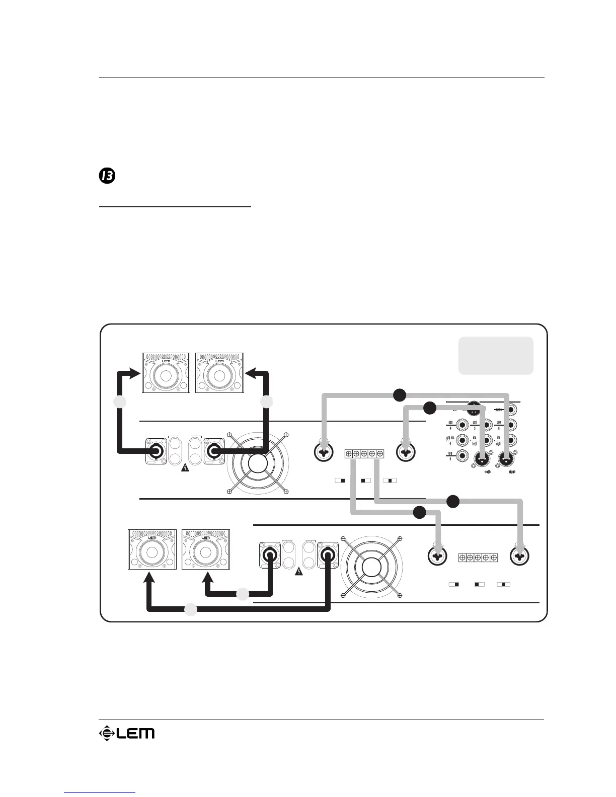
Balanced inputs (0 dB/30 kW): in AMP 4,8 & 12 models both
channel A&B of the amplifier have a double balanced input with
an COMBO connector and a BARRIER STRIP connector connected
in parallel. In this manner, the amplifiers input signal can be
connected to either of these connectors (greatly facilitating
connections) and if necessary, can be passed on to the input of
another amplifier or other units (see é illustrations).
On the AMP 2.4, there is a single balanced input with a JACK
connector for each of the A&B channels.
 Loading...