EasyManua.ls Logo

LEM Avalon AV15-4 User Manual

Default Icon
10 pages
To Next Page IconTo Next Page
Page #1 background imageLoading...
Page #1 background image
1 1
1 1
1
JJ
JJ
J
Soldering point.
Male connector.
Female connector.
M/F faston connector.
Test point.
Supply voltage.
Logic supply ground.
Analog supply ground.
Chassis ground.
Earth ground.
Flag joined with one or more flags
GENERALMUSIC S.p.A. Sales Division: 47842 S.Giovanni in Marignano (RN) ITALY - Via delle Rose, 12 - tel. 0541/959511 - fax 0541/957404
GENERALMUSIC on the NET: http://www.generalmusic.com
SERVICE MANUAL
L
CODE: 270241
M
Warnings
with the same signal name inscribed.
Address
ATTENTION
Observe precautions when handling electrostatic sensitive devices.
Notice
Service must be carried out by qualified personnel only.Any tampering carried out by unqualified personnel during the guarantee period
will forfeit the right to guarantee.
For a correct operation of the instrument, after having switched off, be careful to wait at least 3 seconds before switching on again.
To improve the device's specifications, the schematic diagrams may be subject to change without prior notice.
All components marked by this symbol have special safety characteristics, when replacing any of these components use only
manufacturer's specified parts.
The (µ) micro symbol of capacitance value is substituted by U.
The (
) omega symbol of resistance value is substituted by E.
The electrolytic capacitors are 25Vdc rated voltage unless otherwise specified.
All resistors are 1/8
unless otherwise specified.
All switches shown in the "OFF" position. All DC voltages measured to ground with a voltmeter 20KOhm/V.
Index
Technical Specifications
2
AV12-4, AV12-8, AV15-4, AV15-8, AV15S Passive Versions Schematic Diagrams
2
AV12-4, AV12-8, AV15-4, AV15-8, AV15S Passive Versions Spare Part List
3
4
AV12A Test Procedures & Adjustment
AV12A, AV15A, AV15SA Block Diagrams
3
AV15A Test Procedures & Adjustment
5
AV15SA Test Procedures & Adjustment
5
AV12A Schematic Diagram
8
9
AV15SA Schematic Diagram
AV15A Schematic Diagram
7
10
AV12A, AV15A, AV15SA Active Version Spare Part List
Question and Answer IconNeed help?

Do you have a question about the LEM Avalon AV15-4 and is the answer not in the manual?

LEM Avalon AV15-4 Specifications

General IconGeneral
BrandLEM
ModelAvalon AV15-4
CategorySpeakers
LanguageEnglish

Summary

Warnings

Notice

General safety notice regarding service and tampering during guarantee period.

ATTENTION

Precautions for handling electrostatic sensitive devices.

Address

AVALON TECHNICAL SPECIFICATIONS

Model Specifications

Technical specifications for AV12-4, AV12-8, AV15-4, AV15-8, and AV155 models.

Transistor Packages

Spare Part List (PASSIVE VERSIONS)

Accessories

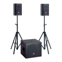
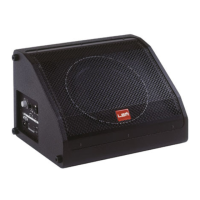
List of accessories for passive speaker versions.

Model Specific Passive Parts

Spare parts categorized by specific passive speaker models.

TEST PROCEDURES & ADJUSTMENTS

General Precautions and Instruments

Safety precautions, remarks, visual checks, and required test instruments.

AV12A Amplified Loudspeaker Procedures

Detailed test procedures, supply check, and channel check for AV12A.

Amplified Loudspeaker Procedures

AV15A Amplified Loudspeaker

Test procedures, supply check, and channel check for AV15A.

AV15SA Amplified Subwoofer

Test procedures, supply check, and channel check for AV15SA.

AV15SA Amplified Subwoofer Procedures

Setup, Supply, and Initial Checks

Setup, supply voltage checks, and initial channel testing for AV15SA.

Advanced Checks and Adjustments

High rail, gain, bias, bandwidth, offset, and SNR checks for AV15SA.

Troubleshooting Advices

Guidance and advice for troubleshooting common issues on the amplifier board.

Spare Part List (ACTIVE VERSIONS)

Accessories

List of accessories for active speaker versions.

Model Specific Active Parts

Spare parts categorized by specific active speaker models.

Related product manuals