3
D400 - TEST PROCEDURES & ADJUSTMENTS
PRECAUTION
• To prevent short circuit during any test, the oscilloscope must be EARTH in su lat ed, this
occurs because some test require to connect its probe to the amplifi er output, non-compliance
may cause damages to oscilloscope inputs circuitry.
• Before removing or installing any modules and connectors, disconnect the am pli fi er from
AC MAINS and measure the DC supply voltages across each of the power supply capacitors.
If your measurement on any of the caps is greater than 10Vdc, connect a 100ohm 50W
resistor across the applicable caps to discharge them for your safety. Remember to remove
the discharge resistor immediately after discharging caps. Do not power up the amplifi er
with the discharge resistor connected.
• Read these notes entirely before proceeding to any operation. These notes are not com-
prehensive of all damages that possibly occur, but includes some specifi cally advices, checks
and adjustments relative to this amplifi ed speaker.
• Do not check the amplifi er with the speakers connected use the appropriate load resistors
only.
• BE CAREFUL increasing the Variac you must not exceed the nominal mains voltage plus
its tolerance (see specifi cations) any upper voltage can be cause of damage.
REMARKS
• This loudspeaker system is processed by a RED 40bit DSP (Digital Signal Processor), the
processor supervise all louspeaker operation such as crossover fi lters, equalization, phase,
delay, peak limiters, long term power protection, LFC low frequency control, anti-feedback,
multicomp and noise gate. These functions are recalled with the 16 PRESET encoder on the
system panel, which include different settings suitable for the use of the system in different
confi gurations. Follow a brief explapanation of each preset:
PRESET Description
1) LEM INDOOR Typical indoor equalization (default preset)
2) LEM OUTDOOR Typical outdoor equalization (more mids)
3) FLAT Without equalization
4) ENTERTAIN Typical entertainer/piano bar equalization
5) MAX LOUD Typical loudness contour equalization for low level listening
6) CD PLAYER Typical DJ, DISCO PUB eq for high level listening (with multicomp)
7) WALL MOUNT Typical wall mount equalization taking in count the 6 dB low boost
8) STAGE MONITOR Typical stage monitor equalization (without anti-feedback)
9) LEM INDOOR SW Same as above with 100Hz HP Filter to use it with Sub Woofer
10) LEM OUTDOOR SW Same as above with 100Hz HP Filter to use it with Sub Woofer
11) FLAT SW Same as above with 100Hz HP Filter to use it with Sub Woofer
12) ENTERTAIN SW Same as above with 100Hz HP Filter to use it with Sub Woofer
13) MAX LOUD SW Same as above with 100Hz HP Filter to use it with Sub Woofer
14) CD PLAYER SW Same as above with 100Hz HP Filter to use it with Sub Woofer
15) WALL MOUNT SW Same as above with 100Hz HP Filter to use it with Sub Woofer
16) MIC PLUG & PLAY Typical voice/mic amplifi cation (with anti-feedback)
IMPORTANT NOTE
• Shorting the internal jumper between pin 1 and 3 of CN1 located on CPU/DSP Board, the
amplifi er is set for testing the amplifi er module alone with a fl at response on each output,
without eq, fi lters, limiters and protections.
BE SURE THAT IS INSERTED WHEN YOU CHECK THE AMPLIFIER ALONE AND REMO-
VED WHEN THE SPEAKERS ARE CONNECTED.
• The amplifi er module is designed with two amplifi ers: a 300W amplifi er for the LF speaker
builded with discrete devices and operating in class H, and a 100W amplifi er for the HF driver
builded with integrated device and operating in class AB.
VISUAL CHECK
• Check the speakers for any damaging (cone-breaking, interruption or further).
• Before proceed to supply the amplifi er check visually the internal assembly, if appears an
evident damage fi nd the most possible reasons that cause it.
• Check the wiring cables for possible interruptions or shorts.
• If the damage has burnt a printed circuit board don’t try to repair it, replace with a new
one.
TEST INSTRUMENTS
• Audio Generator
• Dual Trace Oscilloscope
• Digital Multimeter
• Temperature Meter
• 4ohm 500W, 8ohm 150W, 100ohm 50W resistors
• Variac (0÷250Vac)
TECHNICAL SPECIFICATIONS
Power Requirements: (230Vac±10% 50Hz) 400VA
or (115Vac±10% 50/60Hz) 400VA
Max Low Out Power*: (4ohm) 290W
Max High Out Power*: (8ohm) 64W
Low Out*: (4ohm) 96Vpp
High Out*: (8ohm) 64Vpp
Frequency Response: (-10dB) 45Hz ÷ 20KHz
Frequency X-Over (Low/High) 2.2KHz
Nominal Input Sensitivity: (+4dBu) 1.229V
RMS
Mic Max Input Sensitivity: (-40dBu) 7.75mV
RMS
Input Impedance: (balanced) 30Kohm
(unbalanced) 15Kohm
Voltage Gain: (nominal) 29±1dB
IMD: (SMPTE 60Hz/7KHz 4:1) <0.1%
THD: (THD+N) <0.1%
S/N Ratio: (unweighted) >100dB
* Note: measured with the IHF standard method and without limiters.
SETUP
• Connect the Variac between the mains and the amplifi er and set it at zero voltage.
• Disconnect all the Speakers.
• Turn at centre (nominal level) the VOLUME potentiometer.
• Insert the jumper between pin1 and pin3 of CN1.
• Set the ENCODER rotary switch on preset LEM INDOOR.
• Connect the audio generator to the input and set it to 1000Hz -10dBu (245mV
RMS
) sinu-
soidal signal.
• Connect the oscilloscope probe CH1 to the LOW OUT, clip to - (S3) and tip to + before RL1
(R15 side RL1), set it to 5V/div. 200µS/div.
• Connect the oscilloscope probe CH2 to the HIGH OUT, clip to - (S2) and tip to + (S1), set
it to 5V/div. 200µS/div.
• The load resistors are disconnected.
• The procedures that follow must be executed subsequently in the order specifi ed.
SUPPLY CHECK
• Verify with the Multimeter the insulation between the heatsink and all device packages
(TR1,2,3,4,6,8,14,15,20, IC1,2,3,4).
• Verify with the Multimeter the PTC resistor value, it must be between 50 and 200ohm.
• Remove the transformer secondary fuses, set the Variac to the nominal mains voltage,
check with the Multimeter the AC supply voltages:
F1-F2=93±2Vac.
F3-F4=50±1.5Vac.
• Re-set the Variac at zero voltage, turn off the amplifi er and put the fuses back on its
holders.
• Set up the Variac slowly monitoring the oscilloscope screen, starts from 2/3 of nominal
mains voltage it should display the sinusoidal signal amplifi ed without dis tor tions and without
any DC voltage, if a distortion occur or the protection trips check the amplifi er as suggested
in the ADVICES section.
• When the Variac ac voltage reaches the nominal voltage verify the DC supplies as follow:
TR8 collector pin 3 (+Vcc2) =+63±2Vdc
TR14 collector pin 3 (-Vcc2) =-63±2Vdc
TR2 collector pin 2 (+Vcc1) =+32±2Vdc
TR3 collector pin 2 (-Vcc1) =-32±2Vdc
IC4 pin 3 =+15±1Vdc
IC3 pin 3 =-15±1Vdc
• If one or more voltages don’t correspond, check the rectifi ers, capacitors and transformers
disconnecting them from circuitry, refer to schematics.
INITIAL CHECK (LOW AMPLIFIER)
• Set both channels of the oscilloscope to 10V/div. 200µS/div.
• Increase the input level to -6dBu (0.388V
RMS
) sinusoidal signal.
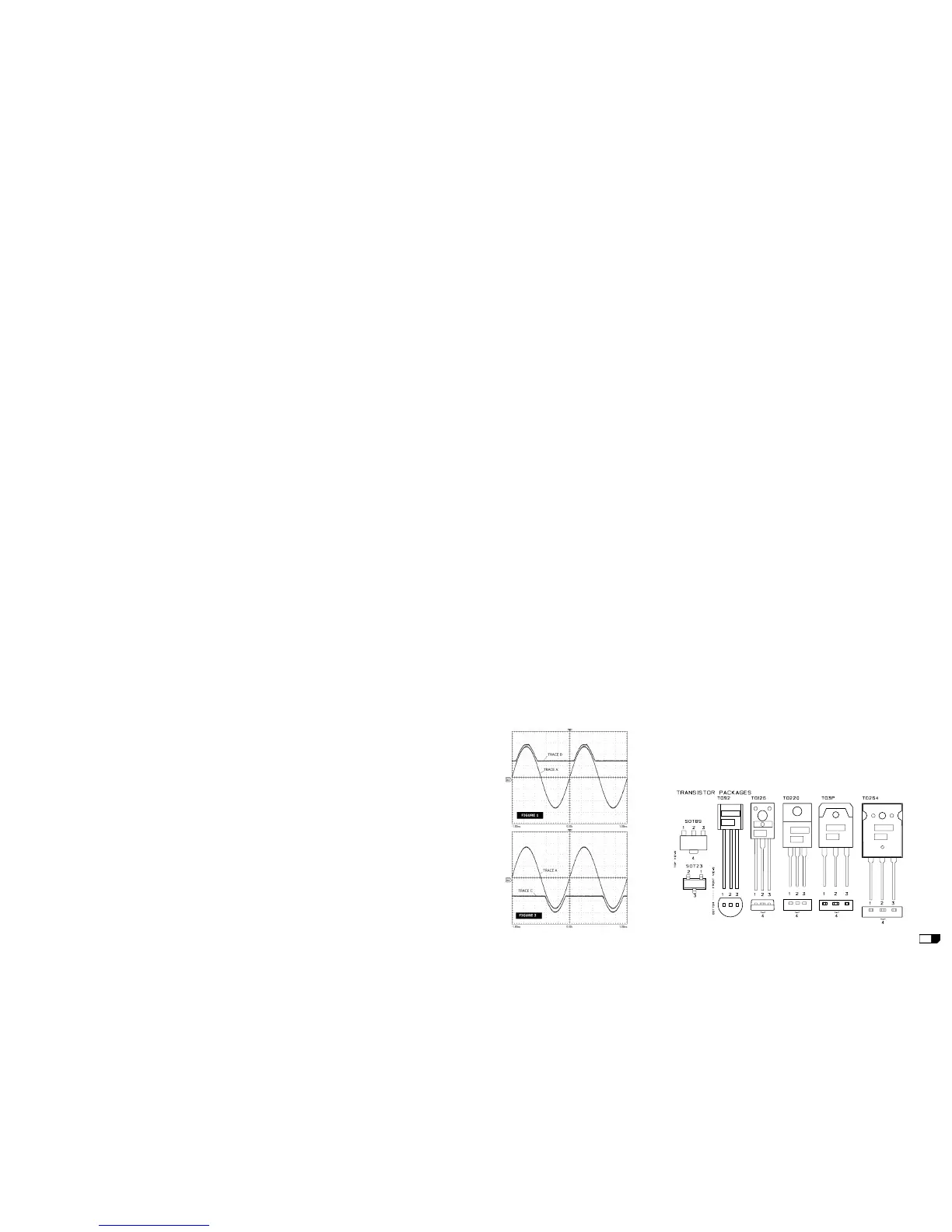
• The channel output signals must be symmetrical respect the GND with an amplitude of
about 25V
PEAK
and without visible distortion or oscil-
lation as shown in Fig.1 Trace A (note: the fi gure is
rep re sent a tive don't refer to its level). If there is a
distortion read the section ADVICES.
HIGH RAIL CHECK (LOW AMPLIFIER)
• Connect the CH2 probe tip to D2 cathode and set
the sensitivity of both channels at 20V/div.
• Increasing the input signal two things should to
happen: till the output signal (Positive half-wave)
is less than 25V
PEAK
the voltage on D2 cathode
have to remain constant at 32V, when the output
signal exceeds 25V
PEAK
the voltage on D2 cathode
will have to follow the output signal with 7V offset
(see Fig.1 Trace B).
• Check the negative high rail connecting the probe
to D3 anode (see Fig.2 Trace C).
• Increase further the input signal till it reaches
about +2dBu (0.976V
RMS
), the amplifi er output
have to reach its maximum output before clipping
at about 60V
PEAK
(48V
PEAK
with load at tached for an
input signal of about +0dBu).
• Connect the 4ohm 500W load on the output and
repeat the INITIAL and HIGH RAIL checks.
PTC TEMPERATURE SENSOR CHECK (LOW AMPLIFIER)
• Heat the PTC sensor with a welder tip, in touch with its body, to verify if this protection
works properly reducing the output signal to few volts with time.
BIAS ADJUSTMENT (LOW AMPLIFIER):
• Set the generator level at zero, connect the Multimeter across the R13 resistor, then adjust
VR1 trimmer to read 5±0.5mVdc.
• Verify the same voltage across R15.
BANDWIDTH CHECK (LOW AMPLIFIER)
• Switch the generator frequency to 100Hz and 10KHz, no level changes respect to 1KHz
must be detectable.
AMPLIFIER CHECK (HIGH AMPLIFIER)
• Set up the generator to 1KHz 0dBu (775mV
RMS
) sinusoidal signal.
• Connect the oscilloscope probe CH2 to the HIGH OUT, clip to - (S2) and tip to + (S1), set
it to 10V/div. 200µS/div.
• The channel output signal must be symmetrical without visible distortion and oscillation
as shown in fi g.1 trace A (note: the fi gure is representative don't refer to its level). If there
is a distortion check IC1 circuitry.
• Increase the input signal, when the input signal reaches about +2dBu (0.976V
RMS
) the
amplifi er output reaches its maximum output before clipping at about 30±2V
PEAK
(27±2V
PEAK
with load at tached and an input signal of about +1dBu).
• Switch the generator frequency to 100Hz and 10KHz, no level changes respect to 1KHz
must be detectable.
• Connect the 8ohm 150W load on output and repeat the check.
MIC INPUT CHECK
• Set up the generator to 1KHz -40dBu (7.75mV
RMS
) sinusoidal signal.
• Rotate full clockwise (max level) the VOLUME potentiometer.
• The CH1 oscilloscope trace attached to LOW output amplifi er must be equal to 60 ±5V
PEAK
(without load attached).
ENCODER & SIGNAL/LIMIT CHECK
• Switch off, wait some seconds and then switch on the amplifi er, a testing loop will start.
• The SIGNAL/LIMIT led lights green for three sec. and red for another three sec.
• Waiting six sec. the led starts to fl ash in green colour, rotate the PRESET encoder on CD
PLAYER SW position, the green led remains lighted for three sec. the CPU/DSP confi rms the
right encoder reading.
• Waiting another three sec. the led starts again to fl ash in green colour, rotate the PRESET
encoder on FLAT position, the red led remains lighted for three sec. to confi rm the right
encoder reading.
• Waiting another three sec. the led starts again to fl ash in green colour, the check is end.
•If you want to start it again, you have to select LEM INDOOR SW, the led switch off for three
sec. and then it fl ashes again, the check it is ready start.
ADVICES
• If the input sinewave appears to be distorted during the negative cycle, you can assume
that the problem is located somewhere in the circuitry of the positive rail.
• If the positive cycle appears distorted, you can assume that the problem is in the circuitry
of the negative low rail. Refer to the schematics.
• If you have determinate that the problem is a short on a supply rail, you must check the
output transistors to determine which transistor devices are bad.
• Use a soldering iron to lift one leg of each emitter pin and measure the emitter-collector
resistance on each device.
• Unsolder and lift one leg of each base pin and check the base-collector resistance of each
transistor and replace any that measure as a short.
• If all the transistors are OK, unsolder and lift one leg of each diode and check them.
• Check the circuit board for open foil traces.
• Use the Multimeter as Ohm-meter to check the resistors, particularly the base and emitter
resistors of damaged transistor.
 Loading...