The Lenco AF 3310 LA-1500M is a stereo main amplifier, designed to deliver high-fidelity audio output. This service manual provides comprehensive information regarding its specifications, front panel features, parts list, adjustment procedures, block diagram, wiring diagram, schematic diagram, and an exploded view for maintenance and repair.
Function Description:
The LA-1500M serves as the core of a stereo audio system, amplifying audio signals from various sources to drive speaker systems. It features two main amplifier channels, indicated by "L-CH POWER AMP" and "R-CH POWER AMP" in the block diagram, each capable of delivering substantial power. A key aspect of its design is the inclusion of a protection circuit, which safeguards the amplifier and connected speakers from damage due to overheating or other electrical anomalies. The unit also incorporates a relay driver and a power supply section to ensure stable and reliable operation. Output level meters provide a visual indication of the audio power being delivered to the speakers, allowing users to monitor performance. Speaker selector switches (A and B) enable the user to choose between different speaker systems or to use both simultaneously.
Important Technical Specifications:
Amplifier Section:
- Continuous average power output (both channels driven):
- Into 8 Ohms (from 20Hz to 20kHz): 180W
- Into 8 Ohms (from 1kHz): 200W
- Total Harmonic Distortion (into 8 Ohms, from 20Hz to 20kHz): 0.08%
- Signal to Noise Ratio (IHF "A" Network): 120dB
- Input (Sensitivity/Impedance): 1V/56kΩ
- Frequency Response: 6Hz to 110kHz (-3dB)
- Power "ON" Muting Time: 5 Sec
Miscellaneous:
- Power requirements: AC220V, 50Hz
- Power Consumption: 620W
- Dimensions: 420(W) x 130(H) x 380(D)mm
Usage Features:
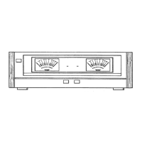
The front panel of the LA-1500M is designed for straightforward operation:
- Power Switch: A simple depress action turns the amplifier on or off, supplying power to the unit.
- Output Level Meters: Two meters provide a visual representation of the audio power delivered to each speaker, allowing users to monitor the output in real-time.
- Protection Circuit Operation Indicator Lamp: This feature includes both a red and a green LED. The red LED illuminates when the protection circuit is active (e.g., during power-on muting or overheating), while the green LED indicates that the protection circuit is off and the amplifier is operating normally. The protection circuit engages for 5-7 seconds upon power-on and whenever the unit's temperature exceeds a specified limit.
- Speaker "A" Selector Switch: Depressing this button connects the amplifier output to speaker system A terminals. When released, sound is not heard from speaker system A.
- Speaker "B" Selector Switch: Similar to the Speaker "A" switch, this button connects the amplifier output to speaker system B terminals when depressed. When released, sound is not heard from speaker system B.
Maintenance Features:
The manual provides detailed information crucial for servicing and maintaining the amplifier:
- Parts List Exterior: This section lists all external components with their part numbers and quantities, facilitating easy identification and replacement of physical parts like the front panel, knobs, screws, and chassis components.
- Electrical Parts List: A comprehensive list of electrical components, including resistors, electrolytic capacitors, ceramic capacitors, mylar capacitors, and styrol capacitors, along with their values and part numbers. This list is essential for troubleshooting and replacing faulty electronic components. Notes on converting resistance values into codes are also provided.
- Adjustment Procedures: Specific instructions are given for adjusting the power meters. This includes:
- Power Meter Adjustment with Power "OFF": Involves removing the front panel and manually adjusting the meter needle to the "0" mark on the scale using VR102.
- Power Meter Adjustment with Power "ON": Requires feeding a 1kHz, 1V RMS signal to the L channel input jack, with speakers and an 8-ohm dummy load connected. VR102 is then adjusted until the L channel meter needle points to "200W" on the scale.
- R Channel Meter Adjustment: VR101 is used to adjust the R channel meter in the same manner as the L channel.
- Block Diagram: A high-level overview of the amplifier's internal structure, showing the interconnections between major functional blocks such as power amplifiers, protection circuit, relay driver, power supply, and power level meters. This helps in understanding the signal flow and overall architecture.
- Wiring Diagram: Illustrates the physical wiring connections between different components and boards, which is invaluable for tracing connections during repair or modification.
- Schematic Diagram: A detailed circuit diagram showing all individual components, their values, and their electrical connections. This is the most critical document for in-depth troubleshooting, component-level repair, and understanding the circuit's operation. It also includes notes on resistor and capacitor specifications, voltage measurements, and other symbols.
- Exploded View: A visual representation of all physical parts assembled, showing how they fit together. This is extremely useful for disassembly and reassembly, ensuring that all components are correctly placed.
Overall, the Lenco AF 3310 LA-1500M is a robust stereo main amplifier designed for high-power audio delivery, with comprehensive documentation provided for its operation, maintenance, and repair.