Dual Reader Interface Module LNL-1320 Series 3 Quick Reference
© 2020 Carrier. All Rights Reserved. LenelS2 is a part of Carrier. 2 QR50L-1034E — revision 3.004
Reader Wiring
Each reader port supports a reader with TTL (D1/D0, Clock/Data), F/2F, or
2-wire RS-485 signaling. Power to the reader is selectable: 12 VDC (VIN
must be greater than 20 VDC), or power is passed-through (PT) from the
input voltage of the LNL-1320 (TB7-VIN), 300 mA maximum per reader
port. Readers that require different voltage or have high current
requirements must be powered separately. (Refer to the reader manufacturer
specifications for cabling requirements.) In the 2-wire LED mode, the
buzzer output is used to drive the second LED. Reader port configuration is
set via the host software.
To fully utilize each reader port:
• TTL signaling requires a 6-conductor cable (18 AWG).
• F/2F signaling requires a 4-conductor cable.
• RS-485 signaling requires two 2-conductor cables. Use one (1) cable
for power (18 AWG) and one (1) cable for communication (24 AWG,
with drain wire and shield).
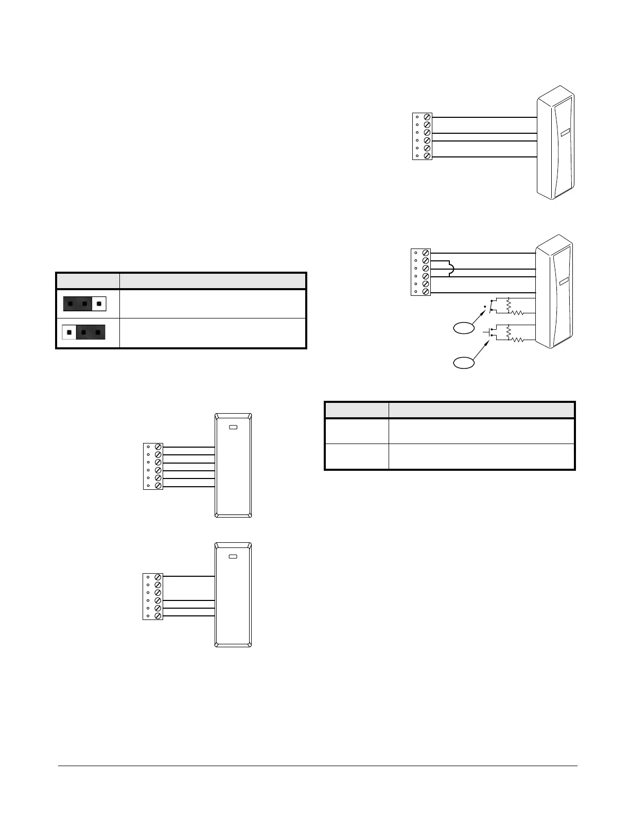
Typical D1/D0 - Clock/Data Reader
Typical 2-Wire RS-485 Device (such as OSDP Reader)
Typical Unsupervised F/2F Reader
Typical Supervised F/2F Reader
Note: Jumper: Connect D1 to LED on supervised F/2F readers.
Alarm Contact Wiring
There are eight (8) inputs that are typically used to monitor door position,
request to exit, or alarm contacts. Input circuits can be configured as:
• Unsupervised alarm (2 states); reporting as an open or closed contact.
• Supervised alarm (6 states); reporting as an open or closed contact,
open circuit, shorted circuit, grounded circuit *, or foreign voltage*.
A supervised input circuit requires adding two (2) resistors with a value of
1k ohm, 1% to the circuit to facilitate proper reporting and should be located
as close to the sensor as possible. Custom end of line (EOL) resistances may
be configured via the host software.
* Grounded and foreign voltage states are not a requirement of UL 294 and
therefore not verified by UL.
The input circuit wiring configurations shown are supported but may not be
typical.
12V PT J1 - Reader Port Power Select
12 VDC is available on reader ports (VIN is greater than or
equal to 20 VDC).
VIN power is “passed through” to reader ports.
Note: Install jumper J1 in the 12V position ONLY if the input
voltage (VIN) is greater than 20 VDC. Failure to do so may
damage the reader to the LNL-1320.
1
VO
LED
BZR
D1/CLK/TR+
D0/DAT/TR-
GND
TB8 or TB9
RED
GRN
WHT
BLK
ORG
BRN
1
VO
LED
BZR
D1/CLK/TR+
D0/DAT/TR-
GND
TB8 or TB9
Typical Supervised F/2F Reader Callouts
Callout Description
1 Door monitor switch
Normally Closed contact*
2 Request to Exit switch
Normally Open contact*
* Inputs on supervised F/2F readers may be unsupervised or supervised.
(Supervised is shown.)
1
VO
LED
BZR
GND
+12 VDC
D1
GROUND
DO (GREEN LED)
F/2F Reader
TB8 or TB9
VO
LED
BZR
D1/CLK/TR+
D0/DAT/TR-
GND
+12 VDC
D1
GROUND
DO (GREEN LED)
1K,1%
1K,1%
1K,1%
1K,1%
1
TB8 or TB9
1
2
F/2F Reader
 Loading...