Dual Reader Interface Module LNL-1320 Series 3 Quick Reference
© 2020 Carrier. All Rights Reserved. LenelS2 is a part of Carrier. 3 QR50L-1034E — revision 3.004
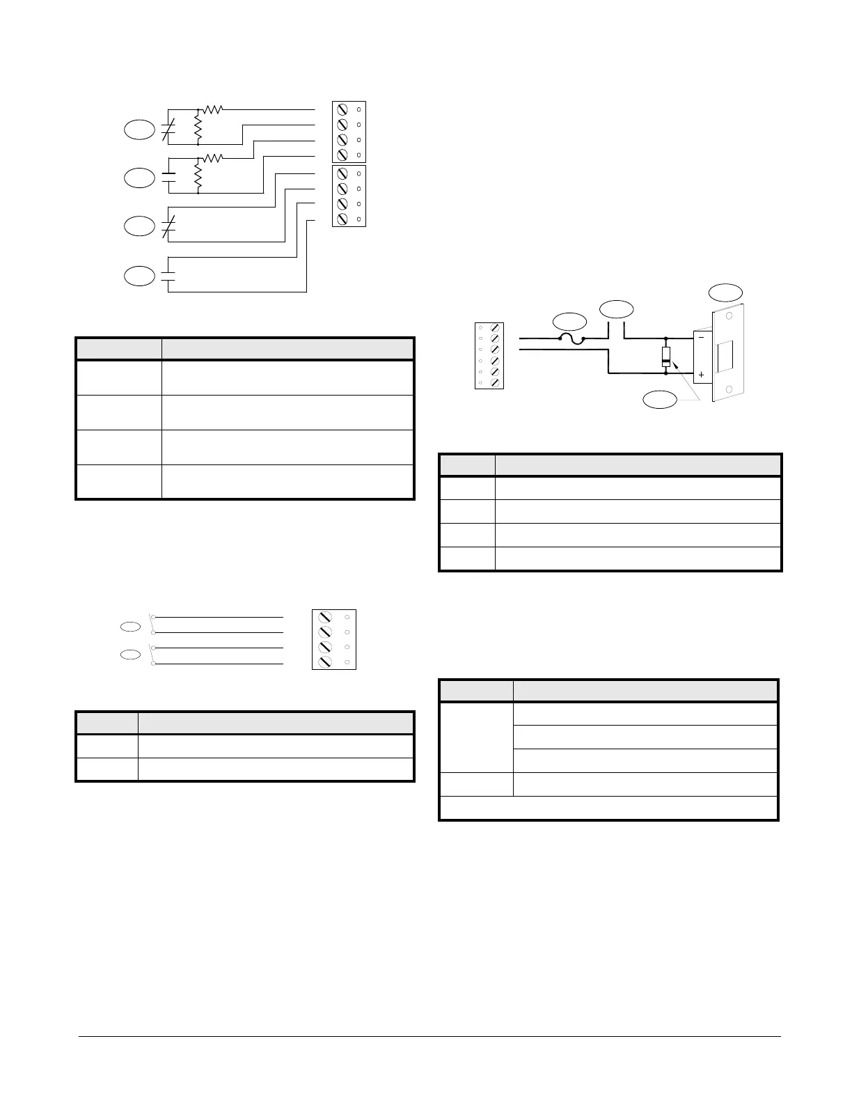
Inputs for Cabinet Tamper/Power Fault
Input CT and input BA are used for monitoring cabinet tamper and power
failure with normally closed contact. These two inputs are for contact
closure monitoring only and do not use EOL resistor(s). If these inputs are
not used, install a short piece of wire at the input to indicate a safe condition.
Output Relay Wiring
Six (6) Form-C contact relays are provided for controlling door strikes or
other devices. Load switching can cause abnormal contact wear and
premature contact failure. Switching of inductive loads (strike) also causes
EMI (electromagnetic interference) which may interfere with normal
operation of other equipment. To minimize premature contact failure and to
increase system reliability, a contact protection circuit must be used. The
following two (2) circuits are recommended. Locate the protection circuit as
close to the load as possible (within 12 inches [30 cm]), as the effectiveness
of the circuit will decrease if it is located farther away.
Use sufficiently large gauge of wires for the load current to avoid voltage
loss.
Diode Selection: Diode current rating: 1x strike current. Diode breakdown
voltage: 4x strike voltage. For 12 VDC or 24 VDC strike, diode 1N4002
(100V/1A) typical.
Jumper and DIP Switch Usage
Alarm Contact Wiring Callouts
Callout Description
1 Standard supervised circuit
Normally Closed contact
2 Standard supervised circuit
Normally Open contact
3 Unsupervised circuit
Normally Closed contact
4 Unsupervised circuit
Normally Open contact
Inputs for Cabinet Tamper/Power Fault Callouts
Callout Description
1 Cabinet tamper
2 Power fault
1K,1%
1K,1%
1K,1%
1K,1%
IN1 IN2 IN3 IN4
1
2
3
4
Output Relay Wiring Callouts
Callout Description
1DC strike
2Diode
3 Fuse
4 To DC power source
Jumper Description
J1 Reader Power Select
12V = 12 VDC at reader ports. *** See note below ***
PT = VIN "passed through" to reader ports
J4 RS-485 Termination, install in first and last units, only
All other jumpers are for factory use only
Note: Install jumper J1 in the 12V position ONLY if the input
voltage (VIN) is greater than 20 VDC. Failure to do so may
damage the reader to the LNL-1320.