Single Reader Interface Module LNL-1300 Series 3 Quick Reference
© 2020 Carrier. All Rights Reserved. LenelS2 is a part of Carrier. 2 QR50L-1033E — revision 3.004
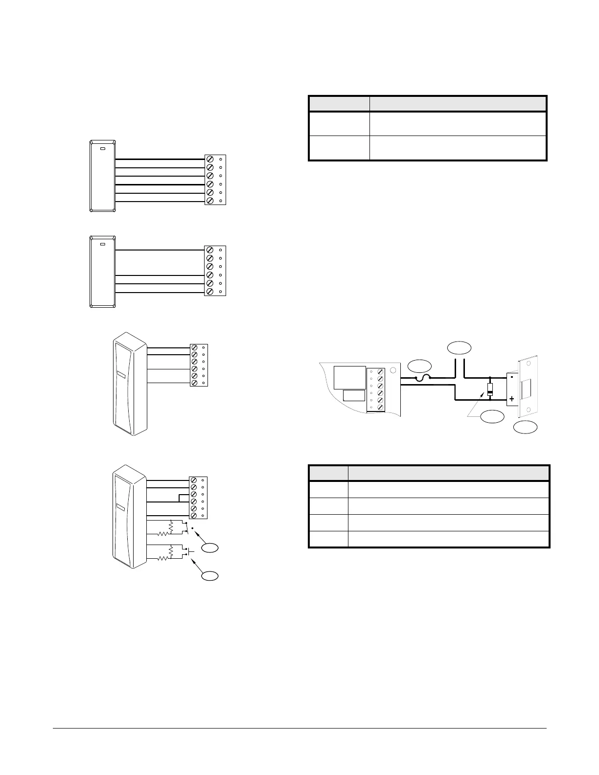
Reader Wring
The reader port supports a reader with TTL (D1/D0, Clock/Data), F/2F, or
2-wire RS-485 signaling. (Refer to the reader manufacture specifications for
cabling requirements.) In the 2-wire LED mode the buzzer output is used to
drive the second LED. Reader port configuration is set via the host software.
Typical D1/D0 or Clock/Data Reader
Typical RS-485 Device (such as OSDP Reader)
Typical Unsupervised F/2F Reader
Typical Supervised F/2F Reader
Note: Jumper D1 to LED on supervised F/2F readers.
Door Strike Relay Wiring
Two (2) Form-C contact relays are provided for controlling door strike or
other devices. See specifications section for the relay contact ratings. Load
switching can cause abnormal contact wear and premature contact failure.
Switching of inductive loads (strike) also causes EMI (electromagnetic
interference) which may interfere with normal operation of other
equipment. To minimize premature contact failure and to increase system
reliability, a contact protection circuit must be used. The following two (2)
circuits are recommended. Locate the protection circuit as close to the load
as possible (within 12 inches [30 cm]), as the effectiveness of the circuit will
decrease if it is located far away.
Typical DC Door Strike Wiring
Diode Selection: Diode current rating: 1x strike current. Diode breakdown
voltage: 4x strike voltage. For 12 VDC or 24 VDC strike, diode 1N4002
(100V/1A) typical.
TB4
GND
D0/DAT/TR-
D1/CLK/TR+
VO
LED
BZR
1
BLK
GRN
WHT
RED
BRN
ORG
TB4
GND
D0/DAT/TR-
D1/CLK/TR+
VO
LED
BZR
1
TB4
D1
GROUND
1
F/2F Reader
+12 VDC
DO (GREEN LED)
GND
D0/DAT/TR-
D1/CLK/TR+
VO
LED
BZR
TB4
D1
GROUND
F/2F Reader
+12 VDC
DO(GREEN LED)
GND
D0/DAT/TR-
D1/CLK/TR+
VO
LED
BZR
1K,1%
1K,1%
1K,1%
1K,1%
1
1
2
Typical Supervised F/2F Reader Callouts
Callout Description
1 Door monitor switch
Normally Closed contact*
2 Request to Exit switch
Normally Open contact*
*Inputs on supervised F/2F readers may be unsupervised or supervised.
(Supervised is shown)
Door Strike Relay Wiring Callouts
Callout Description
1DC strike
2Diode
3 Fuse
4 To DC power strike
+
-
TB3
K2
K1
C
NC
NO
C
NO
NC
K2
K1
1
4
3
2
 Loading...