EasyManua.ls Logo

Lennox 10ACB

Lennox 10ACB
12 pages
To Next Page IconTo Next Page
Loading...
3DJH
£
PRODUCT LITERATURE
¤
1998 Lennox Industries Inc.
Dallas, Texas
VALUE 10
TM
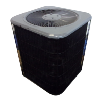
CONDENSING UNIT
Value 10 condensing units are designed for expansion
valve (TXV) and RFC systems. Refer to Lennox engi-
neering handbook for expansion valve kits which must
be ordered separately.
SHIPPING AND PACKING LIST
1-- Assembled 10ACB condensing unit
1-- 45
E
copper street elbow
1-- RFCIV refrigerant metering device (bullet)
1-- Coupling -- 5/16 x 3/8 (18, 24, 30)
Check unit for shipping damage. Consult last carrier
immediately if damage is found.
GENERAL INFORMATION
These instructions are intended as a general guide and
do not supersede national or local codes in any way.
Authorities having jurisdiction should be consulted be-
fore installation.
IMPORTANT
The Clean Air Act of 1990 bans the intentional
venting of refrigerant (CFCs and HCFCs) as of July
1, 1992. Approved methods of recovery, recycling
or reclaiming must be followed. Fines and/or in-
carceration may be levied for non--compliance.
INSTALLATION
INSTRUCTIONS
9DOXH
70
6HULHV
$&% &RQGHQVLQJ 8QLWV
&21'(16,1* 81,76
1--1/2 through 5 ton
503,800M
2/98
Supersedes 503,755M
TABLE OF CONTENTS
VALUE 10 CONDENSING UNIT 1.....................
SHIPPING AND PACKING LIST 1......................
GENERAL INFORMATION 1..........................
10ACB UNIT DIMENSIONS 2.........................
SETTING THE UNIT 3................................
ELECTRICAL 3......................................
PLUMBING 4.......................................
REFRIGERANT METERING DEVICE 4..................
MANIFOLD GAUGE SET 5...........................
LIQUID & SUCTION LINE SERVICE VALVES 5..........
LEAK TESTING 6....................................
EVACUATION 7.....................................
START-UP 8........................................
CHARGING CONSIDERATIONS 8.....................
CHARGING FOR RFC SYSTEMS 9....................
CHARGING FOR TXV SYSTEMS 10...................
SYSTEM OPERATION 10.............................
MAINTENANCE 11..................................
10ACB CHECK POINTS 12............................
RETAIN THESE INSTRUCTIONS
FOR FUTURE REFERENCE
WARNING
Product contains fiberglass wool.
Disturbing the insulation in this product during
installation, maintenance, or repair will expose
you to fiberglass wool. Breathing this may cause
lung cancer. (Fiberglass wool is known to the
State of California to cause cancer.)
Fiberglass wool may also cause respiratory, skin,
and eye irritation.
To reduce exposure to this substance or for further
information, consult material safety data sheets
available from address shown below, or contact
your supervisor.
Lennox Industries Inc.
P.O. Box 799900
Dallas, TX 75379--9900
/LWKR 86$
Question and Answer IconNeed help?

Do you have a question about the Lennox 10ACB and is the answer not in the manual?

Lennox 10ACB Specifications

General IconGeneral
RefrigerantR-410A
HSPF RatingUp to 9.5
Refrigerant TypeR-410A
EfficiencyUp to 9.5 HSPF
StagesSingle Stage
Voltage208/230V
Phase1

Summary

Installation Instructions

10 ACB Unit Dimensions

Setting the Unit

Installation Clearances

Specifies required clearances for unit installation around the perimeter.

Electrical

Line Voltage

Details for connecting line voltage power supply to the unit.

24 V, Class II Circuit

Instructions for making 24V Class II circuit connections.

Plumbing

Sweat Connection Procedure

Step-by-step guide for making sweat connections on refrigerant lines.

Refrigerant Metering Device

RFC Systems

Information on replacing RFCIV with supplied unit or for RFC systems.

Expansion Valve Systems

Manifold Gauge Set

Liquid & Suction Line Service Valves

Leak Testing

Using an Electronic Leak Detector or Halide

Procedure for using leak detection equipment on the system.

Evacuating

Start-Up

Charging Considerations

Charging for RFC Systems

Weighing in the Charge Method

Method for weighing refrigerant charge for RFC systems below 65°F.

The Subcooling Method

Method for subcooling charge for RFC systems at or above 65°F.

Charging for TXV Systems

Weighing in the Charge

Method for weighing refrigerant charge for TXV systems below 60°F.

The Approach Method

Method for approach charge for TXV systems at or above 60°F.

System Operation

Crankcase Heater

Details on internal crankcase heaters for specific unit sizes.

Compressor Start Kit

Information on internal start components for single-phase units.

Timed-Off Control (Option Units ONLY)

Description of timed-off control for system pressure equalization.

High and Low Pressure Switches

Function of high and low pressure switches in option units.

Refrigerant Sight Glass (Option Units ONLY)

Maintenance

Evaporator Coil

Procedure for cleaning and inspecting the evaporator coil.

Indoor Unit

Maintenance steps for the indoor unit, including filters and blower.

Start-Up and Performance Check List

Cooling Section

Checklist items for the cooling section performance.

Thermostat

Checklist items related to thermostat settings and level.

Related product manuals