Do you have a question about the Lennox 10ACC-030-230 and is the answer not in the manual?
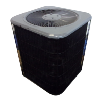
Details the 10ACC residential split-system condensing unit, its sizes, SEER rating, and compressor types.
Highlights critical warnings regarding refrigerant handling, electrical shock, and general safety for installation and service.
Presents electrical specifications including voltage, ampacity, fuse size, and motor ratings for 10ACC models.
Details unit specifications like tonnage, refrigerant connections, coil size, fan motor, and weights for 10ACC models.
Lists optional accessories available for the 10ACC series units, such as crankcase heaters and hail guards.
Covers general safety warnings and an overview of major unit components illustrated in Figure 1.
Illustrates the control box for reciprocating and scroll compressors, showing key components like contactors and capacitors.
Explains the function and operation of the compressor contactor (K1) in the 10ACC unit's control box.
Details the dual capacitor (C12), start capacitor (C7), and potential relay (K31) used in the 10ACC control box.
Explains the design, operation, and unique compression concept of the scroll compressor used in 10ACC units.
Describes how the scroll compressor compresses gas and warns against using it for evacuation due to potential damage.
Explains that the condenser fan motor uses a run capacitor and is controlled by the compressor contactor.
Details how to access the condenser fan motor assembly and replace the motor, referencing Figures 8 and 9.
Covers field refrigerant piping, line set types, and connection sizes for the 10ACC series.
Explains how to operate liquid and suction line service valves, including accessing the Schrader port and closing the valve.
Describes the ball-type full service valve used on 5-ton units and its service port.
Details the process for pumping down the system and performing leak testing before evacuation.
Step-by-step guide for evacuating the system to the required vacuum level, including precautions.
Explains factory charge, adjustments for line set length, and methods based on outdoor temperature.
Guidance on weighing refrigerant charge for fixed orifice or TXV systems, especially in cool weather.
Details how to use the subcooling method to charge fixed orifice systems when outdoor temp is above 65°F.
Explains using the approach method for TXV systems when outdoor temperature is 60°F or above.
Guidance on using Table 5 for performing maintenance checks on system pressures and potential issues.
Instructions for cleaning and inspecting condenser and evaporator coils, including condensate pan.
Covers cleaning filters, adjusting blower speed, checking belts, wiring, voltage, and amp-draw.
Details the sequence of operation for cooling mode, including thermostat demand and component activation.
Identifies key components in the wiring diagram, such as capacitors, contactors, and motors.
The Lennox 10ACC is a residential split-system condensing unit designed for cooling applications. It is available in various sizes, ranging from 1-1/2 to 5 tons, and is engineered to achieve a minimum SEER rating of 10.0. The unit is compatible with either an expansion valve or an RFCIV system in the indoor unit.
The 10ACC unit's primary function is to provide cooling for residential spaces. It operates as part of a split-system, meaning it works in conjunction with an indoor evaporator coil and blower. The condensing unit, located outdoors, compresses and condenses refrigerant, which then circulates to the indoor coil to absorb heat from the indoor air, thus providing cooling.


 Loading...