507266-05 Page 45 of 58Issue 1933
Emergency Replacement Motor Operation
If the variable speed motor needs to be replaced in an
emergency situation (such as “no heat”) and an exact
replacement motor is not immediately available, a standard
PSC motor of equivalent frame size, voltage, rotation, and
horsepower can be temporarily installed until the correct
replacement motor can be obtained.
Connect the desired speed tap to the “ACC” terminal and
the neutral tap to the neutral terminal on the ignition control
(refer to the furnace wiring diagram). The ignition control
will control the motor’s operation, including a nominal 20
second “on” delay with a call for heat and a nominal 180
second “o” delay when the thermostat is satised. It will
also operate the motor on a call for cooling, with no “on” or
“o” delays.
Verify that the unit is operating at the desired speed and
within the rise range as shown on the unit rating plate.
The correct replacement motor must be installed as soon
as possible to ensure continued satisfactory operation of
the furnace.
Control Diagnostics
Troubleshooting
Make the following visual checks before troubleshooting:
1. Check to see that the power to the furnace and the
integrated ignition/blower control board is ON.
2. The manual shuto valves in the gas line to the furnace
must be open.
3. Make sure all wiring connections are secure.
4. Review the Sequence of Operation.
Start the system by setting thermostat above room
temperature. Observe system response. Then use the
information provided in this section to check the system
operation.
The furnace has a built-in, self-diagnostic capability. If a
system problem occurs, a fault code is shown by a red LED
on the control board. The control continuously monitors its
own operation and the operation of the system. If a failure
occurs, the LED will indicate the failure code. The ash
codes are presented in Table 10.
Fault Code History Button
The control stores the last ve fault codes in memory. A
push-button switch is located on the control. When the
push-button switch is pressed and released, the control
ashes the stored fault codes. The most recent fault code
is ashed rst; the oldest fault code is ashed last. To clear
the fault code history, press and hold the push-button
switch in for more than 5 seconds before releasing.
High Heat State LED
On 95G2UHV models, a green LED is provided on the
control board to indicate high heat state (see Table 11).
CFM LED
On 95G2UHV models equipped with a variable speed
motor, an amber LED is provided on the control board to
display CFM. To determine what CFM the motor is delivering
at any time, count the number of times the amber LED
ashes. Each ash signies 100 CFM; count the ashes
and multiply by 100 to determine the actual CFM delivered
(for example: 10 ashes x 100 = 1000 CFM).
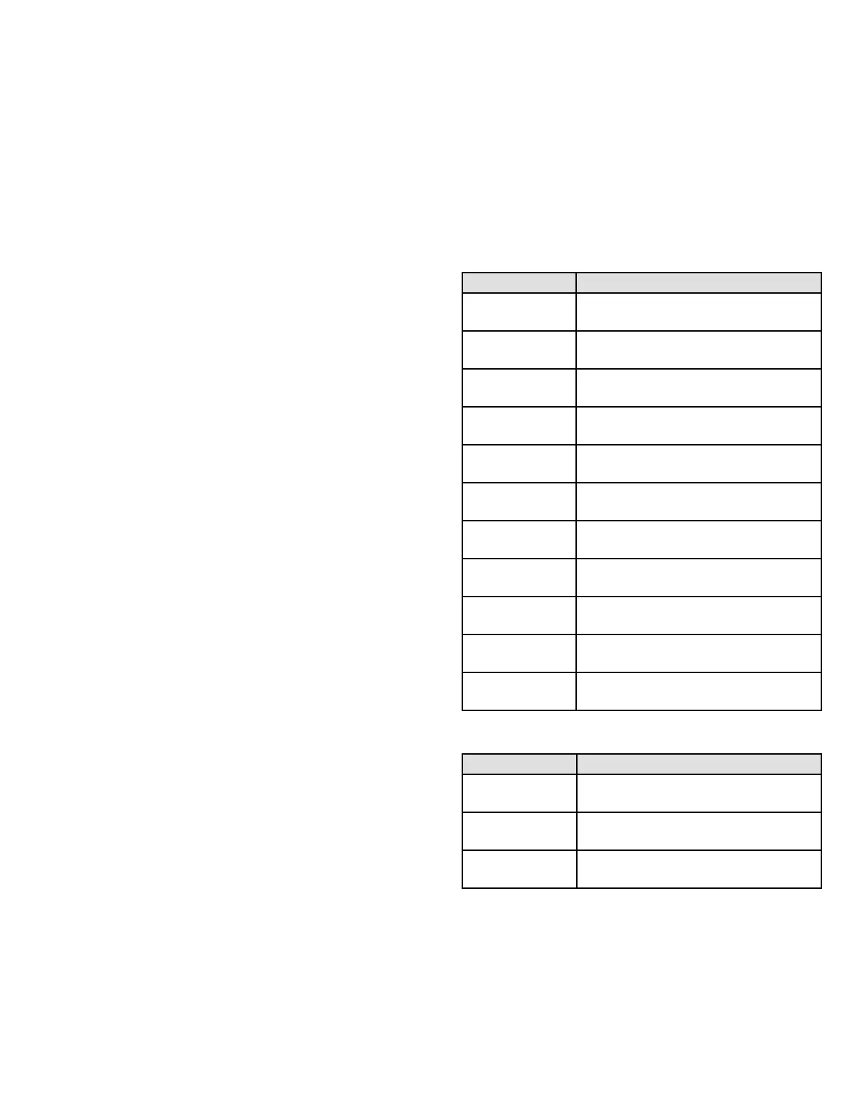
Table 10. Failure Codes - Red LED
LED Status Fault Description
LED O
No power to control or control hardware
fault detected
LED On Normal operation
1 Flash Flame present with gas valve o
2 Flashes Pressure switch closed with inducer o
3 Flashes
Low-re pressure, rollout, or aux limit
switch open
4 Flashes High limit switch open
5 Flashes Not used
6 Flashes Pressure switch cycle lockout
7 Flashes Lockout due to no ignition
8 Flashes Lockout due to too many ame dropouts
9 Flashes Incorrect polarity and phasing
Table 11. High Heat State - Green LED
LED Status Description
LED O No demand for high heat
LED On High heat demand, operating normally
LED Flashing
High heat demand, high pressure switch
not closed
 Loading...