EasyManua.ls Logo

Lennox Carel pGD1 - User Manual

Lennox Carel pGD1
4 pages
Print Icon
To Next Page IconTo Next Page
Loading...
1LNX74-543.3
THIS MANUAL IS THE PROPERTY OF THE OWNER.
PLEASE LEAVE IT WITH THE OWNER WHEN YOU LEAVE THE JOB.
Application
The pGD1 is a remote user interface for the Carel controller
that is available to be used on all model "DLV" Packaged
Ventilation/Dedicated Outside Air System (DOAS) Units.
The interface allows a user to access the Carel controller
remotely for setpoint changes and to view the operational
status of the equipment. The interface features an LED
backlit graphic display and buttons for excellent visibility. Also
included is a buzzer to indicate alarm conditions. The interface
can be used as a handheld device or can be wall mounted.
Two common uses for the pGD1:
When servicing the unit, depending on factors such as unit
size or roof curb height, the unit mounted controller may
require a ladder to access. Having the ability to navigate
through the controller menus from roof level may be easier
with this device.
Maintenance personnel may wish to have the pGD1
mounted in an equipment control room.
Note: The pGD1 does not have temperature/humidity control
capabilities. It is only meant as an interface to the Carel
controller menu structure remotely. For space temperature/
humidity sensing/control, please refer to the literature for the
Carel pAD.
August, 2021
INSTALLATION INSTRUCTIONS
Carel pGD1 Digital Display/Interface Module
Packaged Ventilation/Dedicated Outside Air System (DOAS)
model DLV
LNX74-543.3
5H0816770002
1. The use of this manual is specifically intended
for a qualified installation and service agency.
All installation and service of these kits must be
performed by a qualified installation and service
agency.
2. These instructions must also be used in
conjunction with the Installation and Service
Manual originally shipped with the unit, in addition
to any other accompanying component supplier
literature.
IMPORTANT
Figure 1.1 - Carel pGD1 Display/Interface Module
Model Number: PGD1000WX0
Power Supply Input: 24 Vac (powered from unit controller)
Operating
Conditions:
-4°F to 140°F
10 to 85% Relative Humidity
(non-condensing)
Index of Protection: IP40 (NEMA Type 1)
Maximum Wired
Distance:
100 feet using RJ12 cable
Dimensions: 6.14” W x 1.22” D x 3.23” H
WARNING
1. Disconnect power supply before making wiring
connections to prevent electrical shock and
equipment damage.
2. All units must be wired strictly in accordance with
wiring diagram furnished with the unit. Any wiring
different from the wiring diagram could result in a
hazard to persons and property.
3. All wiring must be done with a wiring material
having a temperature rating of at least 105°C.
Question and Answer IconNeed help?

Do you have a question about the Lennox Carel pGD1 and is the answer not in the manual?

Summary

Carel pGD1 Installation and Operation

Product Application and Safety

Covers the pGD1's purpose, common uses, and critical safety warnings for installation.

Installation Methods

Details procedures for both handheld and wall mounting of the pGD1 interface.

Wiring and Controller Connection

Explains how to connect the pGD1 to the unit controller, including distance limits and port options.

Button Functions and Configuration

Describes the pGD1's buttons and how to address it within the Carel controller.

Overview

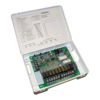
The Carel pGD1 Digital Display/Interface Module is a remote user interface designed for Carel controllers, specifically for use with Lennox "DLV" Packaged Ventilation/Dedicated Outside Air System (DOAS) Units. This module allows users to remotely access the Carel controller to make setpoint changes and monitor the operational status of the equipment.

Function Description:

The pGD1 serves as a remote interface, providing a convenient way to interact with the Carel controller without direct access to the unit-mounted controller. This is particularly useful for servicing units where the controller might be difficult to reach (e.g., due to unit size or roof curb height) or for maintenance personnel who prefer to monitor and adjust settings from a control room. The module features an LED backlit graphic display and six buttons for navigation and control, ensuring excellent visibility and ease of use. It also includes a buzzer to indicate alarm conditions, enhancing operational awareness. It's important to note that the pGD1 itself does not have temperature/humidity control capabilities; its primary role is to interface with the Carel controller's menu structure. For space temperature/humidity sensing and control, users should refer to the Carel pAD literature.

Important Technical Specifications:

  • Model Number: PGD1000WX0
  • Power Supply Input: 24 Vac (powered from the unit controller)
  • Operating Conditions:
    • Temperature: -4°F to 140°F
    • Humidity: 10 to 85% Relative Humidity (non-condensing)
  • Index of Protection: IP40 (NEMA Type 1)
  • Maximum Wired Distance: 100 feet using RJ12 cable
  • Dimensions: 6.14" W x 1.22" D x 3.23" H

Usage Features:

The pGD1 can be used in two primary ways: as a handheld device or wall-mounted.

Handheld Installation:

For handheld use, an RJ12 cable (not exceeding 100 feet in length) is connected to the back of the pGD1. The other end of the cable connects to the unit-mounted controller. If the distance between the pGD1 and the Carel controller exceeds 100 feet, additional Carel literature should be consulted.

Wall Installation:

For wall mounting, the back of the interface module and the front trim plate are removed. The back of the module is then attached to a standard 2" x 4" electrical box mounted sideways using supplied round-head screws. An RJ12 cable (not exceeding 100 feet) is connected to the back of the pGD1. The pGD1 controller is then attached to the mounted back using flush-head screws, and the front trim plate is installed.

Wiring Connection at Unit Controller:

The pGD1 interface must be wired to the unit within 100 feet. If the distance exceeds 100 feet, refer to Carel literature. The wiring varies by unit model and configuration:

  • Direct to Unit Controller: The RJ12 cable connects to the J10 connection on the unit-mounted controller (applies to all units).
  • Units with External Data Port Option: For B and C-Cabinet units with this option, the RJ12 cable connects to an external data port on the exterior of the cabinet.

Button Features:

The pGD1 has six buttons for control:

  • Alarm Button: Press once to view active alarm information (red if active alarms). Press twice to reset any active manual-reset alarms.
  • PRG Button: Selects the main navigation menu.
  • ESC Button: Returns to the main display screen showing unit status.
  • UP Button: Scrolls through display screens (cursor in top left) or increases a setpoint adjustment value.
  • ENTER Button: Confirms setpoint adjustments and moves the cursor to the next available setpoint.
  • DOWN Button: Scrolls through display screens (cursor in top left) or decreases a setpoint adjustment value.

Addressing the pGD1 in the Carel Controller:

Typically, the unit controller automatically recognizes the pGD1 when connected. If not, the address must be set manually:

  1. Press and hold UP+DOWN+ENTER simultaneously until "Display Address" screen appears.
  2. Verify "Display address setting" is 32 and "I/O Board address" is 01 (for PCO3, 5, or OEM+) or 02 (for PCOxs).
  3. If settings are incorrect, press ENTER to access "Terminal Config" screen.
  4. Press ENTER again to view the terminal configuration screen.
  5. Press ENTER until the cursor is under the Trm1 setting, then use UP/DOWN to change the value to 32.
  6. Press ENTER until the cursor is under Pr or Sh. Use UP/DOWN to change to Pr for units without Energy Recovery (Model Digit 7=A, C, D, F, or R) or Sh for units with Energy Recovery (Model Digit 7=B or E).
  7. Press ENTER until the cursor is under No. Use UP/DOWN to change to Yes and press ENTER to complete programming.

Maintenance Features:

The pGD1 simplifies maintenance by allowing technicians to access controller menus from a more convenient location, reducing the need for ladders or direct access to the unit-mounted controller, especially on large or roof-mounted units. The robust IP40 (NEMA Type 1) protection rating ensures durability in typical control room or indoor environments. The use of standard RJ12 cabling for connection also facilitates easy installation and replacement if needed.

Lennox Carel pGD1 Specifications

General IconGeneral
BrandLennox
ModelCarel pGD1
CategoryControl Unit
LanguageEnglish

Related product manuals