Page 16
2
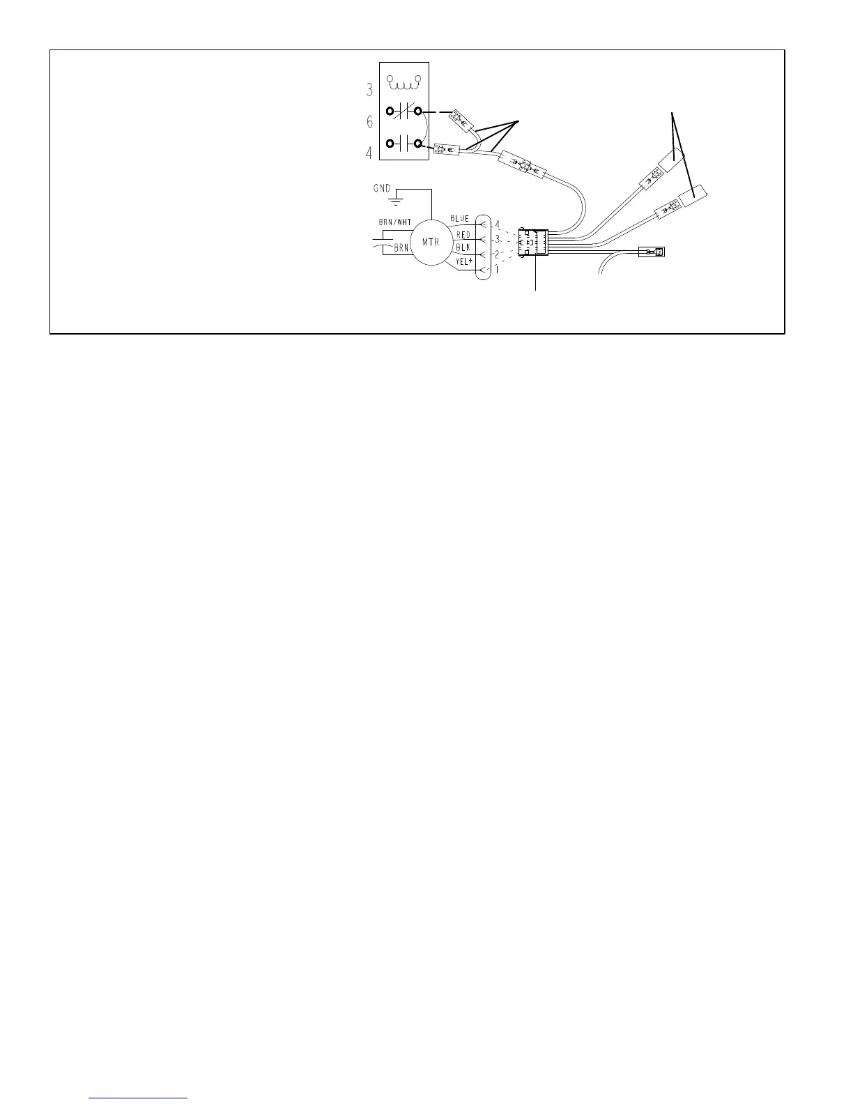
BLUE (MED)
RED (L0)
BLACK (HI)
YELLOW (COM)
5
BLOWER RELAY
BLOWER RELAY
PLASTIC CAPS
4-PIN
BLOWER CONNECTOR
HARNESS
NOTE - Refer to wiring diagram located on the
unit access panel, this figure and blower perform
ance (table 2).
S All air data measured external to unit with 1
inch non-pleated air filter in place.
S All factory settings are medium speed except
the -48 which is set to low speed from the
factory.
S All data given while air handler is operating
with a dry DX coil.
Figure 20. Changing Blower Speed
Table 2. CBX25UH Blower Performance (3-Speed PSC) - 240V (CFM @ ESP. - in. W. C.)
Air Handler
Model
Blower Speed .10" WC .20" WC .30" WC .40" WC .50" WC
-018
Low (Red)
Med (Blue)
High (Black)
510
670
905
495
650
865
475
630
820
420
595
770
325
505
705
-024
Low (Red)
Med (Blue)
High (Black)
630
885
1130
625
875
1100
615
850
1070
610
820
1010
580
780
950
-030
Low (Red)
Med (Blue)
High (Black)
900
1075
1240
865
1060
1210
830
1030
1170
780
985
1135
740
940
1085
-036
Low (Red)
Med (Blue)
High (Black)
1075
1300
1510
1040
1250
1450
1000
1205
1390
950
1145
1320
900
1085
1245
-042
Low (Red)
Med (Blue)
High (Black)
1325
1490
1820
1315
1465
1770
1300
1440
1690
1275
1395
1600
1225
1315
1500
-048
Low (Red)
Med (Blue)
High (Black)
1775
1995
2070
1710
1895
1970
1645
1800
1850
1565
1685
1719
1470
1560
1595
-060
Low (Red)
Med (Blue)
High (Black)
1675
1965
2140
1630
1925
2085
1580
1875
2000
1520
1800
1895
1450
1695
1795
S Blower Performance (CFM vs. ESP inches H2O)
S Cooling speeds should not be reduced below factory setting.
S -024 through -060 units with electric heat approved at 0.5" maximum and medium blower speed minimum.
S -018 units with electric heat approved at 0.3" maximum and medium blower speed minimum.

 Loading...