EasyManua.ls Logo

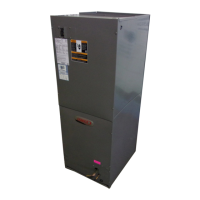
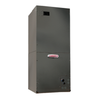
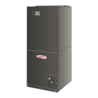
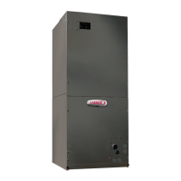
Lennox CBX25UH User Manual

Lennox CBX25UH
20 pages
To Next Page IconTo Next Page
Page #1 background imageLoading...
Page #1 background image
Page 1
E2016 Lennox Industries Inc.
Dallas, Texas, USA
THIS MANUAL MUST BE LEFT WITH THE
HOMEOWNER FOR FUTURE REFERENCE
WARNING
Improper installation, adjustment, alteration, service or
maintenance can cause personal injury, loss of life, or
damage to property.
Installation and service must be performed by a licensed
professional installer (or equivalent) or a service agency.
IMPORTANT
The Clean Air Act of 1990 bans the intentional venting of
refrigerant (CFCs, HCFCs and HFCs) as of July 1, 1992.
Approved methods of recovery, recycling or reclaiming
must be followed. Fines and/or incarceration may be
levied for noncompliance.
INSTALLATION
INSTRUCTIONS
Merit
®
CBX25UH (-10) Series
Units
AIR HANDLERS
507600-03
9/2016
Shipping and Packing List
Package 1 of 1 contains the following:
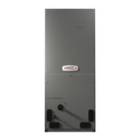
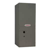
1 - Assembled air handler unit factory-equipped for
upflow or horizontal air discharge application (includes
upflow and horizontal drain pans and pre-installed air
filter).
Check equipment for shipping damage. If found,
immediately report damage to the last carrier. Check the
unit rating plate to confirm that delivered unit matches
order.
General
The CBX25UH air handler is designed for indoor
installation only. As shipped, the unit is ready for
installation in either upflow, horizontal left-hand or
right-hand air discharge applications. Electric heat,
downflow air discharge kits, air filters and other
accessories are available and listed in the CBX25UH
Product Specification bulletin for ordering.
All units are shipped with a factory-installed
check/expansion valve.
WARNING
This product contains a chemical known to the State of
California to cause cancer, birth defects, or other repro
ductive harm.
IMPORTANT INFORMATION FOR INSTALLER
This unit has a delay relay that delays the supply blower “ON for 1 second and keeps the blower “ON for 45
seconds on all fan and cooling demands. For more details, refer to page 17 for unit sequence of operation.
1
SECOND
DELAY
OFF
100%
CFM
100%
CFM
45
SECS
COOLING
DEMAND
1
2
34
Question and Answer IconNeed help?

Do you have a question about the Lennox CBX25UH and is the answer not in the manual?

Lennox CBX25UH Specifications

General IconGeneral
TypeAir Handler
BrandLennox
ModelCBX25UH
Cooling CapacityUp to 5 tons
AirflowUp to 2000 CFM
RefrigerantR-410A
Voltage208/230V
DimensionsVaries by model
WeightVaries by model
Filter TypeStandard 1" Filter
Coil TypeCopper tube with aluminum fins
Motor TypeVariable Speed

Summary

Installation Instructions and Safety

Important Installer Information

Details about delay relays and unit sequence of operation.

Requirements and Safety

General Safety Warnings and Precautions

Covers weight hazards, sharp edges, explosion risks, and electrical shock.

Installation and Operational Guidelines

Addresses condensation, clearance, and accessibility for servicing.

Installation Clearances and Setup

Non-Ducted Return Closet Installation

Specifies minimum open area for louvers in closet installations.

Installation Procedures

Refrigerant Metering Device and Upflow Application

Covers check/expansion valve and upflow unit placement.

Horizontal Application and Left-Hand Discharge

Details horizontal setup, drain pan, and left-hand discharge.

Right-Hand Air Discharge Installation

Component Removal for RH Discharge

Steps for removing blower, coil, drain pan, and brackets.

Right-Hand Air Discharge Reassembly

Reinstalling Components and Panels

Steps for reassembling coil, drain pan, and access panels.

Condensate Drain System

Trap Requirements and Venting

Explains trap installation for primary and overflow drains, plus venting.

Sloping the Unit for Proper Drainage

Details the required slope for effective condensate removal.

Condensate Drain Installation and Testing

Drain Line Connections and Testing

Covers connecting drain fittings, trap installation, and testing procedures.

Filters and Duct System

Air Filter Specifications and Selection

Lists filter sizes and discusses high-efficiency filter impact.

Duct System Installation Guidelines

Covers supply and return duct connections and insulation.

Refrigerant Line Brazing

Handling Refrigerant Lines and System Integrity

Emphasizes clean, dry lines and protecting components during brazing.

Brazing Safety Precautions

Fire and Explosion Hazard Warnings

Alerts to risks from refrigerant ignition and high-pressure gas.

Health and Handling Cautions

Advises on avoiding vapors, wearing protection, and washing hands.

Brazing Procedure Steps

Preparation and Line Connection

Details removing panels, plugs, and connecting refrigerant lines.

Nitrogen Flow and Brazing Execution

Outlines nitrogen purging, rag placement, and brazing techniques.

Unit Sealing and Insulation

Air-Tight Sealing for Moisture Control

Stresses sealing cabinet openings and plenums to prevent moisture.

Electrical Connection Safety

General Electrical Safety Warnings

Covers shock hazards, grounding, and conductor types.

Electrical Connections and Voltage Conversion

Unit Wiring and Grounding

Explains factory configuration, wiring, and grounding requirements.

208 Volt Conversion Procedure

Details steps to convert the unit from 240V to 208V.

Low Voltage Wiring Diagrams

Cooling and Heat Pump Wiring Configurations

Illustrates wiring for cooling, heat pump, and electric heat applications.

Blower Speed Adjustment

Safety and Procedure for Changing Blower Speed

Outlines safety steps and the process for adjusting blower speed.

System Check-Out Procedures

Pre-Start-Up and Component Checks

Lists checks for installation, wiring, and components before operation.

Blower and Cooling Operation Checks

Details how to verify blower and cooling system functionality.

Electric Heater Operation Check

Instructions for verifying the electric heater operation.

System Operation Modes

Blower Time Delay and Cooling Operation

Explains blower delays and sequence for cooling mode.

Heating Operation Modes

Describes operation for electric heat and heat pump heating.

Maintenance and Unit Use

Filter Maintenance and Cabinet Insulation

Covers filter inspection/replacement and insulation repair.

Unit Use During Construction Guidelines

Specifies conditions for using the unit during building construction.

Related product manuals