Page 9
CBX25UH SERIES
FILTERS
A filter is provided. Table 1 lists the filter size for each unit.
Table 1. Unit Air Filter Size Chart
Model Filter Size Actual Minimum
Filter Size
-018 12” x 20” x 1 11.50” x 19.50” x .75”
-024 and -030 15” x 20” x 1 14.50” x 19.50” x .75”
-036 18” x 20” x 1 17.50” x 19.50” x .75”
-042, -048 and -060 18” x 24” x 1 17.50” x 23.50” x .75”
IMPORTANT
If a highefficiency filter is being installed as part of this
system to ensure better indoor air quality, the filter must
be properly sized. Highefficiency filters have a higher
static pressure drop than standardefficiency glass/foam
filters. If the pressure drop is too great, system capacity
and performance may be reduced. The pressure drop
may also cause the limit to trip more frequently during the
winter and the indoor coil to freeze in the summer, result
ing in an increase in the number of service calls.
Before using any filter with this system, check the spe
cifications provided by the filter manufacturer against the
data given in the appropriate Lennox Product Specifica
tions bulletin. Additional information is provided in Ser
vice and Application Note ACC002 (August 2000).
INSTALLING DUCT SYSTEM
Connect supply air duct to the flange on top of the air
handler. If an isolation connector is used, it must be
nonflammable.
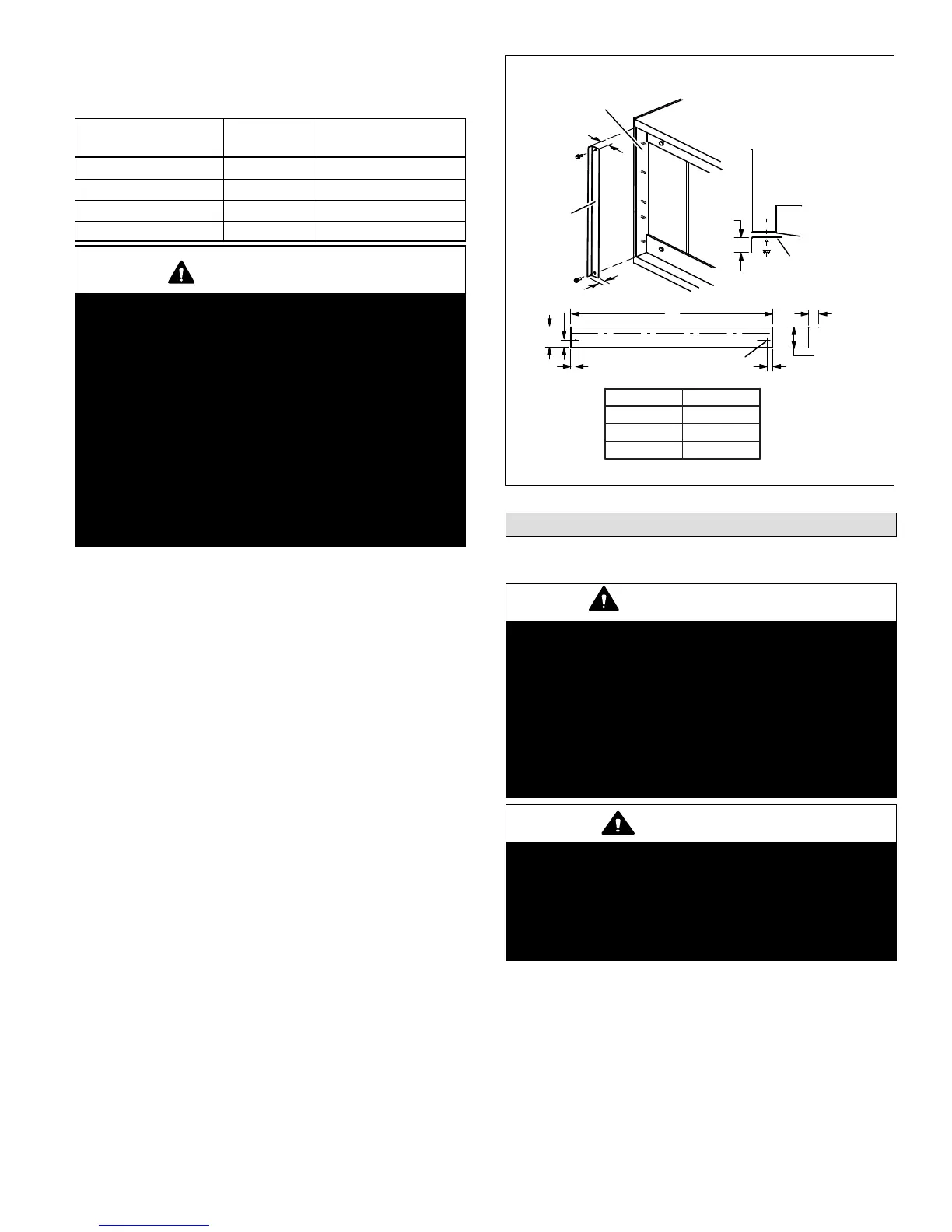
FIELD-FABRICATED RETURN AIR DUCT FLANGE
FOR HORIZONTAL APPLICATIONS
A return air duct system is recommended, but not
factory-provided. If the unit is installed in a confined space or
closet, run a full-size return connection to a location outside the
closet.
BOTTOM OF
CABINET
DUCT
ADAPTER
1−1/2
(38)
”A”
BRAKE DOWN 90 DEGREES
1/4 (6) DIA.
2−HOLES
”A”
−018 14−7/8 (378)
−024 & −030 18−3/8 (467)
−036 to −060 21−3/4 (552)
1−1/2(38)
3/4
(19)
3/4
(19)
1−1/2
(38)
3/4
(19)
1/2
(13)
3/4
(19)
DUCT
FLANGE
CABINET
DOOR FLANGE
UNIT SIZE
Cabinet and Duct Flange
Figure 13. Cabinet and Duct Flange
Brazing Refrigerant Lines
Refrigerant lines must be connected by a qualified
technician in accordance with established procedures.
IMPORTANT
Refrigerant lines must be clean, dry, refrigerant-grade
copper lines. Air handler coils should be installed only
with specified line sizes for approved system combina
tions.
Handle the refrigerant lines gently during the installation
process. Sharp bends or kinks in the lines will cause a
restriction.
Do not remove the caps from the lines or system connec
tion points until connections are ready to be completed.
WARNING
Polyol ester (POE) oils used with HFC-410A
refrigerant absorb moisture very quickly. It is very
important that the refrigerant system be kept closed as
much as possible. DO NOT remove line set caps or
service valve stub caps until you are ready to make
connections.

 Loading...