EasyManua.ls Logo

Lennox CHA16-024 User Manual

Lennox CHA16-024
67 pages
To Next Page IconTo Next Page
Page #1 background imageLoading...
Page #1 background image
Page 1
2001 Lennox Industries Inc.
Litho U.S.A.
Corp. 0109-L2
Service Literature
CHA/CHP16
CHP20
2 to 5 ton (7.0 to 17.6 kW)
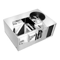
CHA/CHP16, CHP20 SERIES UNITS
CHA/CHP16 and CHP20 series units in the 2 through 5 ton
(7.0 through 17.6 kW) sizes are designed for outdoor roofĆ
top or ground level installations in light commercial applicaĆ
tions. Electric heat is available in several kW sizes. Models
are available in single or three phase power supply and can
be utilized in downflow or horizontal supply and return air.
CHA/CHP16-024/030 model units are equipped with a
reciprocating compressor. CHA/CHP16-036/060 and
CHP20-024/060 model units are equipped with scroll
compressors. The scroll compressor offers high voluĆ
metric efficiency, quiet operation and the ability to start
under system load. Continuous flank contact, mainĆ
tained by centrifugal force, minimizes gas leakage and
maximizes efficiency. The motor is internally protected
from excessive current and temperature.
CHA/CHP16 and CHP20 model units are designed to acĆ
cept any of several different thermostat control systems
with minimum field wiring. Control options such as econĆ
omizer, warm up kit, Honeywell T7300 thermostat or
Honeywell T8600/T8611/T8621 thermostat controls
connect to the unit with jackĆplugs. When plugged in the
controls become an integral part of the unit wiring. Low
voltage thermostat connections facilitate thermostat
field wiring.
Optional electric heat is field installed. Electric heat operĆ
ates in single or multiple stages depending on the kW size.
5kW through 25 kW sizes are available for the CHA/CHP16
and CHP20 units.
Information in this manual is for use by a qualified service
technicial only. All specifications in this manual are subject
to change. Procedures outlined in this manual are repesĆ
ented as a recommendation only and do not supersede or
replace state or local codes.
IMPORTANT
Improper installation, adjustment, alteration, service
or maintenance can cause property damage, personĆ
al injury or loss of life. Installation and service must
be performed by a qualified installer, service agency
or the gas supplier.
WARNING
Electric shock hazard. Can cause injury
or death. Before attempting to perform
any service or maintenance, turn the
electrical power to unit OFF at disconĆ
nect switch(es). Unit may have multiple
power supplies.
WARNING
Refrigerant can be harmful if it is inhaled. Refrigerant
must be used and recovered responsibly.
Failure to follow this warning may result in personal
injury or death.
Question and Answer IconNeed help?

Do you have a question about the Lennox CHA16-024 and is the answer not in the manual?

Lennox CHA16-024 Specifications

General IconGeneral
BrandLennox
ModelCHA16-024
CategoryAir Conditioner
LanguageEnglish

Summary

UNIT INFORMATION

CHA/CHP16, CHP20 SERIES UNITS

Overview of CHA/CHP16 and CHP20 series units for commercial applications.

IMPORTANT SAFETY INFORMATION

Warnings about installation, adjustment, alteration, service, or maintenance.

SPECIFICATIONS

SPECIFICATIONS CHA16

Technical specifications for CHA16 models.

SPECIFICATIONS CHP16

Technical specifications for CHP16 models.

SPECIFICATIONS CHP20

Technical specifications for CHP20 models.

OPTIONAL ACCESSORIES

OPTIONAL ACCESSORIES CHA/CHP16

List of optional accessories for CHA/CHP16 units.

OPTIONAL ACCESSORIES CHP20

List of optional accessories for CHP20 units.

ELECTRICAL DATA

ELECTRICAL DATA CHA16

Electrical data for CHA16 units across various configurations.

ELECTRICAL DATA CHP16

Electrical data for CHP16 units across various configurations.

ELECTRICAL DATA CHP20

Electrical data for CHP20 units across various configurations.

BLOWER DATA

BLOWER DATA CHA16

Blower performance data for CHA16 units at various speeds and pressures.

BLOWER DATA CHP16/20

Blower performance data for CHP16/20 units at various speeds and pressures.

UNIT COMPONENTS

PARTS ARRANGEMENT

Visual layout of major components within the unit.

CONTROL BOX COMPONENTS

Diagram and list of components within the unit's control box.

II-UNIT COMPONENTS (Cont.)

Control Box Components

Detailed description of components within the control box.

Key Control Components

Descriptions of Transformer T1, Contactor K1, Relay K3, and Relay K4.

II-UNIT COMPONENTS (Cont.)

Additional Unit Components

Descriptions of Start Capacitor C7, Dual Capacitor C12, Fan Relay K10, Latch Relay K6, Transfer Relay K8, Potential Relay K31.

II-UNIT COMPONENTS (Cont.)

Defrost Control CMC1

Solid state control for automatic switching between heating and defrost modes.

Defrost Control Timing and Terminals

Details on timing pins, jumper, and terminal functions for defrost control.

Cooling Components

Reciprocating Compressor

Description of reciprocating compressors and their protection features.

COOLING COMPONENTS (Cont.)

CHP16-024/030 Cooling Components Diagram

Diagram showing cooling components for specific models.

COOLING COMPONENTS (Cont.)

CHA/CHP16-048/060, CHP20-042/048/060 Cooling Components Diagram

Diagram showing cooling components for specific models.

Scroll Compressor

Scroll Compressor Description

Detailed explanation of scroll compressor design, operation, and properties.

Component Descriptions

Evaporator Coil, Condenser Coil, and Switches

Descriptions of coils, freezestat switch, and high pressure switch.

Reversing Valve L1

Description of the valve that reverses refrigerant flow.

Component Descriptions (Cont.)

Drier, Defrost Controls, and Low Ambient Controls

Descriptions of drier, defrost thermostat/switch, and low ambient controls.

Condenser Fan and Indoor Blower

Information on condenser fan and indoor blower motors and capacitors.

III-OPTIONAL ECH16 ELECTRIC HEAT

Matchups and Ratings

Tables showing ECH16 electric heat matchups and electrical ratings.

Electric Heat Components

Description of electric heating elements and sequencing controls.

Relay, Contactor, Resistor, and Pilot Relay Functions

Functions of K15, K16, K17 relays, K15 contactor, R6 resistor, and K43 relay.

III-OPTIONAL ECH16 ELECTRIC HEAT (Cont.)

Thermal Relays, Fuses, and High Temperature Limits

Description of thermal relays, fuses, and primary/secondary high temperature limits.

Heating Elements and Time Delay DL2

Description of heating elements and the time delay relay.

IV-PLACEMENT AND INSTALLATION

Installation Requirements

Ensure unit is installed per instructions and codes, using RMF16 if needed.

V-ELECTRICAL CONNECTIONS

Field Wiring

Information on unit and thermostat field wiring connections.

Power Supply

Details on power supply connections, voltage, and wiring.

VI-START-UP - OPERATION

Crankcase Heaters and Preliminary Check

Energizing heaters and performing pre-start checks for safety and functionality.

VII-COOLING SYSTEM SERVICE CHECKS

Gauge Manifold Attachment and Cooling Start Up

Attaching gauges and starting the unit in cooling mode.

Compressor Rotation and Charging

Ensuring correct three-phase compressor rotation and system charging.

VIII-HEATING SYSTEM SERVICE CHECKS

Heat Pump and Optional Electric Heat Checks

Steps for checking heating system operation in heat pump and electric heat modes.

IX-INDOOR BLOWER OPERATION / ADJUSTMENT

Blower Operation and Static Pressure Measurement

How the blower operates and how to measure static pressure.

Blower Operation Adjustment

How to adjust blower speed by changing motor taps.

X-MAINTENANCE

Lubrication, Filters, and Condenser Coil

Guidelines for motor lubrication, filter maintenance, and condenser coil cleaning.

Electrical Checks

Checks for wiring, voltage, and amp-draw of motors.

XI-ACCESSORIES

Mounting Frame and Economizers

Information on mounting frames and economizer types.

Economizer Operation and Enthalpy Control

How economizers operate and adjust using enthalpy control.

Enthalpy Control: Setpoint Control

Adjusting the setpoint for enthalpy control to manage outdoor air intake.

XI-ACCESSORIES (Cont.)

Economizer Adjustments and Sensors

Details on minimum positioner, enthalpy sensor, and mixed air sensor.

Optional Accessory Kits

Information on Night Relay, Warm Up Kit, Coil Guard, Filter Kit, Timed-Off Control, Compressor Monitor.

XI-ACCESSORIES (Cont.)

Low Ambient Kit and Related Components

Details on Low Ambient Kit, its adjustment, and related power/transition kits.

Diffusers and Filter Switch Kit

Optional diffusers and the filter switch kit.

XII-Wiring Diagrams and Operation Sequence

CHP16/20 P VOLTAGE Wiring Diagram

Wiring diagram for P voltage units.

XII-Wiring Diagrams and Operation Sequence (Cont.)

Operation Sequences

Step-by-step explanation of cooling, heating, and defrost operation sequences.

XII-Wiring Diagrams and Operation Sequence (Cont.)

CHP16/20 Y VOLTAGE Wiring Diagram

Wiring diagram for Y voltage units.

XII-Wiring Diagrams and Operation Sequence (Cont.)

CHP16/20 G VOLTAGE Wiring Diagram

Wiring diagram for G voltage units.

XII-Wiring Diagrams and Operation Sequence (Cont.)

Y and G VOLTAGE SEQUENCE OF OPERATION

Operation sequence for Y and G voltage units.

XII-Wiring Diagrams and Operation Sequence (Cont.)

P VOLTAGE SEQUENCE OF OPERATION

Operation sequence for P voltage units.

CHA16 P VOLTAGE Wiring Diagram

CHA16 G, J VOLTAGE Wiring Diagram

ECH16-5kW-P VOLTAGE Wiring Diagram

ECH16 5kW P VOLTAGE SEQUENCE OF OPERATION

Sequence of operation for 5kW P voltage electric heat units.

ECH16-7/10kW-P VOLTAGE Wiring Diagram

ECH16-7/10kW-P VOLTAGE SEQUENCE OF OPERATION

Sequence of operation for 7/10kW P voltage electric heat units.

ECH16 15/ 25kW P VOLTAGE Wiring Diagram

ECH16 15/ 25kW P VOLTAGE SEQUENCE OF OPERATION

Sequence of operation for 15/25kW P voltage electric heat units.

ECH16-5/15kW Y VOLTAGE Wiring Diagram

ECH16-5/15kW Y VOLTAGE SEQUENCE OF OPERATION

Sequence of operation for 5/15kW Y voltage electric heat units.

ECH16-20/25kW Y VOLTAGE Wiring Diagram

ECH16-20 / 25kW Y VOLTAGE SEQUENCE OF OPERATION

Sequence of operation for 20/25kW Y voltage electric heat units.

ECH16-20 / 25kW G, J, M VOLTAGE SEQUENCE OF OPERATION

ELECTROMECHANICAL THERMOSTAT WITH ECONOMIZER

Operation Sequence

Sequence of operations for thermostats with economizers.

ELECTROMECHANICAL THERMOSTAT WITH ECONOMIZER (Cont.)

Enthalpy Control Operation Sequences

Operation sequences for enthalpy low/high, 1st/2nd stage cooling.

Related product manuals