DC60-DM60-ROOFTOP-IOM-1310-E - 30 -
‘DM60’, Installation 5
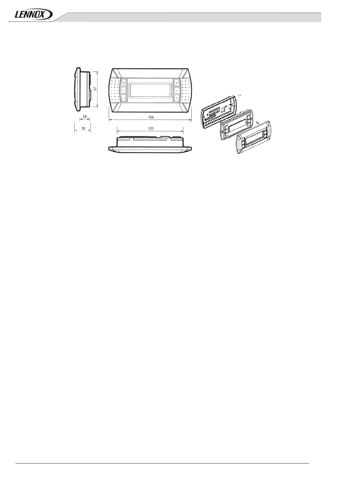
The "DM60" was designed for wall mounting.
The optional DM60 delivered is designed to be wall mounted.
Positioning the cable through the rear
Fasten the rear wall using button head screws provided in the package.
Connect the cable from the main board on the jack on the back of the screen DM60
Attaching the front panel on the back using countersunk screws provided.
Snap frame.
5.1 Connection
WARNING: Separate as much as possible probes, displays, logical input cables
from power cables with strong inductive load, in order to avoid possible
electromagnetic perturbations.
5.1.1 Important warning
An error connecting to the display immediately causes the deterioration of this one
or BM60.
Any wiring modification on the CLIMATIC 60 must be done by Lennox technician or employees having valid
electrical qualification and authorization.
5.1.2
Power supply
The 'DM60' is powered by the BM60.
5.1.3
Communication
The 'DM60' is controlled by a communication bus: RS485 2 wires.
5.1.4
Cable Features
The connection of power and communication must be made by the following cable:
- For a length of 0 to 300m: AWG22 (0.34 mm ²), two crossed pairs with screen.
- For a length of 0 to 500m: LiYCY-P (0.34 mm ²), two pairs shielded general.
The cable length should not exceed 500m.
For better protection of electromagnetic disturbances Lennox recommends the installation of cable LiYCY-P
 Loading...