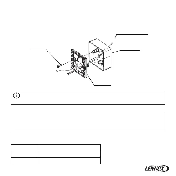
Figure 3.6
To X1/X2 of indoor unit
Cross recessed
head screw
Electrical box
Rear cover of
wired controller
3-3-4 Take the shielded wiring that has been pre-embedded in the wall, and thread it through
the wire hole of the rear cover. Use the Philips head screws (accessory 1) to fix the rear cover
of the wired controller to the electrical box via the support bars. Make sure that the rear cover
is not deformed after being installed (see Figure 3.6).
3-4-1 Wiring specification
• The rear cover may be deformed if the screw is too tight.
• Prepare the electrical box and the 2-core shielded copper wire on site.
• Do not touch the PCB of the wired controller.
Important
Caution
△
!
3-4 Wiring
6
Type 2-core shielded copper wire
AWG 16-20
Maximum 200m
Diameter
Length
Table 3.1
 Loading...