Page 47
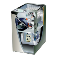
Blower Speeds
Follow the steps below to change the blower speeds.
1 - 7XUQRႇHOHFWULFDOSRZHUWRIXUQDFH
2 - Remove blower access panel.
3 - Disconnect existing speed tap at integrated control
speed terminal.
NOTE - 7HUPLQDWLRQRIDQ\XQXVHGPRWRUOHDGVPXVWEH
LQVXODWHG
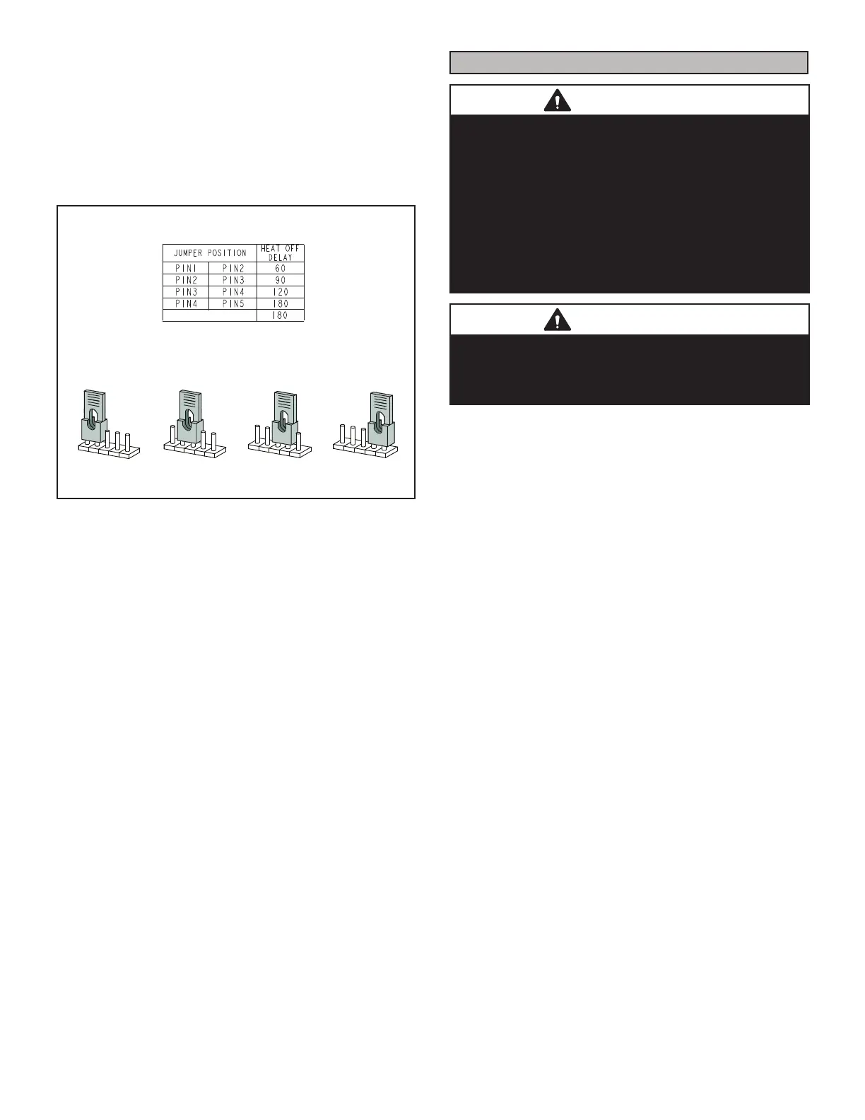
HEAT FAN‐OFF TIME IN SECONDS
To adjust fan-off timing, reposition jumper across pins to
achieve desired setting.
NO JUMPER
60
90
120
180
60
90
120
180
60
90
120
180
60
90
120
180
60 Second
off Time
90 Second
off Time
120 Second
off Time
180 Second
off Time
Figure 62
4 - Place unused blower speed tap on integrated control
“PARK” terminal or insulate.
5 - Refer to blower speed selection chart on unit wiring
diagram for desired heating or cooling speed. See
TABLE 17 on page 54 for allowable heating
speeds.
6 - Connect selected speed tap at integrated control
speed terminal.
7 - Resecure blower access panel.
8 - Turn on electrical power to furnace.
9 - Recheck temperature rise.
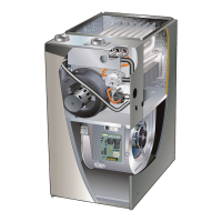
Electronic Ignition
The integrated control has an added feature of an internal
Watchguard control. The feature serves as an automat-
ic reset device for integrated control lockout caused by
ignition failure. This type of lockout is usually due to low
gas line pressure. After one hour of continuous thermostat
demand for heat, the Watchguard will break and remake
thermostat demand to the furnace and automatically reset
the integrated control to begin the ignition sequence.
Exhaust and Air Intake Pipe
1 - Check exhaust and air intake connections for
tightness and to make sure there is no blockage.
2 - Is pressure switch closed? Obstructed exhaust pipe
ZLOOFDXVHXQLWWRVKXWRႇDWSUHVVXUHVZLWFK&KHFN
termination for blockages.
3 - Obstructed pipe or termination may cause rollout
VZLWFKHV WR RSHQ 5HVHW PDQXDO ÀDPH UROORXW
switches on burner box assembly if necessary.
Service
WARNING
ELECTRICAL SHOCK, FIRE,
OR EXPLOSION HAZARD.
Failure to follow safety warnings exactly could result in
dangerous operation, serious injury, death or property
damage. Improper servicing could result in dangerous
operation, serious injury, death, or property damage.
Before servicing, disconnect all electrical power to
furnace. When servicing controls, label all wires prior to
disconnecting. Take care to reconnect wires correctly.
Verify proper operation after servicing.
WARNING
The blower access panel must be securely in place when
the blower and burners are operating. Gas fumes, which
could contain carbon monoxide, can be drawn into living
space resulting in personal injury or death.
Annual Furnace Maintenance
At the beginning of each heating season, and to comply
with the Lennox Limited Warranty, your system should be
checked as follows:
1 - Check wiring for loose connections, voltage at
indoor unit and amperage of indoor motor.
2- Check the condition of the belt and shaft bearings if
applicable.
3- Inspect all gas pipe and connections for leaks.
&KHFN WKH FOHDQOLQHVV RI ¿OWHUV DQG FKDQJH LI
necessary (monthly).
5- Check the condition and cleanliness of burners and
heat exchanger and clean if necessary.
6- Check the cleanliness of blower assembly and
clean the housing, blower wheel and blower motor if
necessary.
7- Inspect the condensate drain and trap for leaks and
cracks. The drain and trap must also be cleaned
and the trap must be primed with water. Inspect the
rubber hoses connected to the pressure switches for
cracks or loose connections, replace as necessary.
Remove the rubber hoses from the cold end header
box and inspect for any blockage, clean as needed.
If strainers are installed in the hoses remember to
remove and clean before reinstalling the hoses.
8- Evaluate the heat exchanger integrity by inspecting
the heat exchanger per the AHRI heat exchanger
inspection procedure. This procedure can be viewed
at www.ahrinet.org
(QVXUH VXႈFLHQW FRPEXVWLRQ DLU LV DYDLODEOH WR WKH
furnace. Fresh air grilles and louvers (on the unit and
in the room where the furnace is installed) must be
SURSHUO\ VL]HG RSHQ DQG XQREVWUXFWHG WR SURYLGH
combustion air.
 Loading...