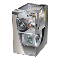
Page 39
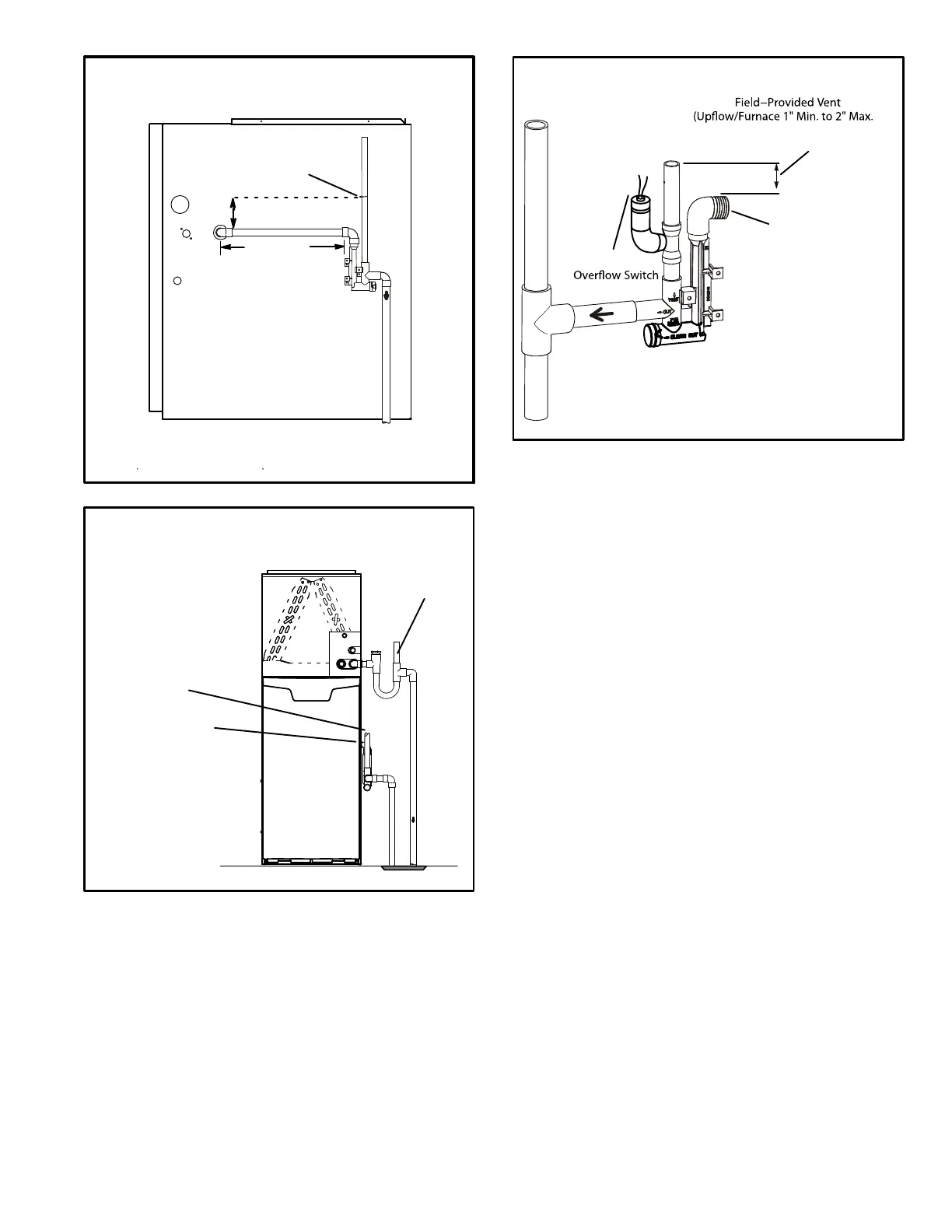
FIGURE 48
(Unit shown in upflow position with remote trap)
*5’ max.
To Drain
PVCPipeOnly
FieldProvidedVent
Min. 1” AboveCondensate
Drain
Connection
1”
Min.
Trap Can Be Installed a
Maximum 5’ From Furnac
e
2” Max.
CONDENSATE TRAP LOCATIONS
*Piping from furnace must slope down a
minimum 1/4” per ft. toward trap
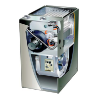
FIGURE 49
EL196UHE With Evaporator
Coil Using A Separate Drain
Condensate
DrainConnection
Field Provided Vent
(1” min. 2” max. above
condensate connection)
Evaporator drain
line required.
Trap optional.
FIGURE 50
Horizontal Furnace 4” Min. to 5” Max.above
condensatedrain connection)
FurnaceCondensate
DrainConnection
From Evaporator Coil
Optional
Condensate Trap With Optional Overflow Switch
 Loading...