Page 51
Cleaning Heat Exchanger
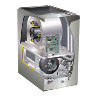
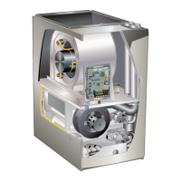
If cleaning the heat exchanger becomes necessary, follow
the below procedures and refer to gure 1 when disas-
sembling unit. Use papers or protective covering in front of
furnace while removing heat exchanger assembly.
1 - Turn o electrical and gas supplies to the furnace.
2 - Remove the furnace access panels.
3 - Disconnect the wires from the gas valve.
4 - Remove gas supply line connected to gas valve.
Remove the burner box cover (if equipped) and
remove gas valve/manifold assembly.
5 - Remove sensor wire from sensor. Disconnect
2-pinplug from the ignitor.
6 - Disconnect wires from ame roll-out switches.
7 - Loosen clamps at vent elbow. Disconnect
condensate drain tubing from ue collar. and
remove the vent elbow.
8 - Loosen clamps and remove combustion air intake
exible connector if equipped.
9 - Remove four burner box screws at the vestibule
panel and remove burner box. Set burner box
assembly aside.
NOTE - If necessary, clean burners at this time.
Follow procedures outlined in Burner Cleaning
section.
10 - Mark and disconnect all combustion air pressure
tubing from cold end header collector box.
11 - Mark and remove wires from pressure switch
assembly. Remove pressure switch assembly.
Keep tubing ttached to pressure switch assembly.
12 - 12 - Disconnect the plug from the combustion air
inducer. Remove two screws which secure combustion
air inducer to collector box. Remove combustion air
inducer assembly. Remove ground wire from vest
panel.
13 - Remove electrical junction box from the side of the
furnace.
14 - Disconnect condensate line from cold end header
box. Remove cold end header box.
15 - Loosen clamps on exhaust and air intake pipe seal
plate. Slide exhaust and intake pipes up and out to
clear blower deck. Remove exhaust and air intake
pipe seal plate.
16 - Mark and disconnect any remaining wiring to
heating compartment components. Disengage
strain relief bushing and pull wiring and bushing
through the hole in the blower deck.
17 - Remove the primary limit from the vestibule panel.
18 - Remove two screws from the front cabinet ange
at the blower deck. Spread cabinet sides slightly to
allow clearance for removal of heat exchanger.
19 - Remove screws along vestibule sides which secure
vestibule panel and heat exchanger assembly to
cabinet. Remove two screws from blower rail which
secure top heat exchanger ange. Remove heat
exchanger from furnace cabinet.
20 - Back wash heat exchanger with soapy water
solution or steam. If steam is used it must be below
275°F (135°C) .
21 - Thoroughly rinse and drain the heat exchanger.
Soap solutions can be corrosive. Take care to rinse
entire assembly.
22 - Reinstall heat exchanger into cabinet making sure
that the clamshells of the heat exchanger assembly
are engaged properly into the support bracket on
the blower deck. Remove the indoor blower to view
this area through the blower opening.
23 - Re-secure the supporting screws along the vestibule
sides and top to the cabinet.
24 - Reinstall cabinet screws on front ange at blower
deck.
25 - Reinstall the primary limit on the vestibule panel.
26 - Route heating component wiring through hole in
blower deck and reinsert strain relief bushing.
27 - Reinstall electrical junction box.
28 - Reinstall exhaust and air intake pipe seal plate.
Reinstall exhaust and air intake pipes and tighten
clamps on pipe seal plate.
29 - Reinstall the cold end header box.
30 - Reinstall the combustion air inducer. Reconnect the
combustion air inducer to the wire harness.
31 - Reinstall pressure switch assembly and reconnect
pressure switch wiring.
32 - Carefully connect combustion air pressure switch
tubing from pressure switches to proper ports on
cold end header collector box.
33 - Reinstall condensate trap.
34 - Secure burner box assembly to vestibule panel
using four existing screws. Make sure burners line
up in enter of burner ports.
35 - Reconnect exhaust piping and exhaust drain tubing.
36 - Reconnect ame roll-out switch wires.
37 - Reconnect sensor wire and reconnect 2-pin plug
from ignitor.
38 - Reinstall gas valve manifold assembly. Reconnect
gas supply line to gas valve.
39 - Reinstall burner box cover if equipped.
40 - Reconnect plug to gas valve.
41 - Replace the blower compartment access panel.
42 - Follow lighting instructions on unit nameplate to
light and operate furnace for 5 minutes to ensure
the furnace is operating properly.
43 - Check all piping connections, factory and eld, for
gas leaks. Use a leak detecting solution or other
preferred means.
44 - Replace access panel.
CAUTION
Some soaps used for leak detection are corrosive
to certain metals. Carefully rinse piping thoroughly
after leak test has been completed. Do not use
matches, candles, ame or other sources of ignition
to check for gas leaks.
 Loading...