Page 74
2 - On eld supplied terminations for side wall exit,
exhaust piping may extend a maximum of 12 inches
(305MM) for 2” PVC and 20 inches (508MM) for 3”
(76MM) PVC beyond the outside wall.
3 - If exhaust piping must be run up a side wall
to position above snow accumulation or other
obstructions, piping must be supported every 24
inches (610MM). When exhaust piping must be run
up an outside wall, any reduction in exhaust pipe
size must be done after the nal elbow.
4 - Distance between exhaust pipe terminations on
multiple furnaces must meet local codes.
NON-DIRECT VENT ROOF TERMINATION KIT
UNCONDITIONED
ATTIC SPACE
3” (76mm) OR
2” (51mm) PVC
PROVIDE SUPPORT
FOR EXHAUST LINES
12” (305mm)
ABOVE AVE.
SNOW
TION
FIGURE 41
NOTE - Do
tical discharge through an existing unused chimney or stack is required, insert piping
inside
trated. In any exterior portion of chimney, the exhaust vent must be insulated.
STRAIGHT-CUT OR
ANGLE-CUT IN DIRECTION
OF ROOF SLOPE
SHOULDER OF FITTINGS
PROVIDE SUPPORT
OF PIPE ON TOP PLATE
EXTERIOR
PORTION OF
CHIMNEY
INSULATE
TO FORM
SEAL
SHEET
METAL TOP
PLATE
NON-DIRECT VENT APPLICATION
USING EXISTING CHIMNEY
Minimum 12” (305MM)
above chimney top
plate or average snow
accumulation
FIGURE 42
Condensate Piping
This unit is designed for either right- or left-side exit of
condensate piping in upow applications. In horizontal
applications, the condensate trap must extend below the
unit. An 8” service clearance is required for the conden-
sate trap. Refer to FIGURE 43 for condensate trap loca-
tions. FIGURE 51 shows trap assembly
NOTE - If necessary the condensate trap may be installed
up to 5’ away from the furnace. Use PVC pipe to connect
trap to furnace condensate outlet. Piping from furnace
must slope down a minimum of 1/4” per ft. toward trap.
1 - Determine which side condensate piping will exit
the unit, location of trap, eld-provided ttings and
length of PVC pipe required to reach available
drain.
2 - Use a large at head screw driver or a 1/2” drive
socket extension and remove plug (Figure 45) from
the cold end header box at the appropriate location
on the side of the unit. Install provided 3/4 NPT
street elbow tting into cold end header box. Use
Teon tape or appropriate pipe dope.
NOTE - Cold end header box drain plugs are factory
installed. Check the unused plug for tightness to
prevent leakage.
3 - Install the cap over the clean out opening at the
base of the trap. Secure with clamp. See FIGURE
51.
4 - Install drain trap using appropriate PVC ttings,
glue all joints. Glue the provided drain trap as
shown in FIGURE 55. Route the condensate line
to an open drain. Condensate line must maintain a
1/4” downward slope from the furnace to the drain.
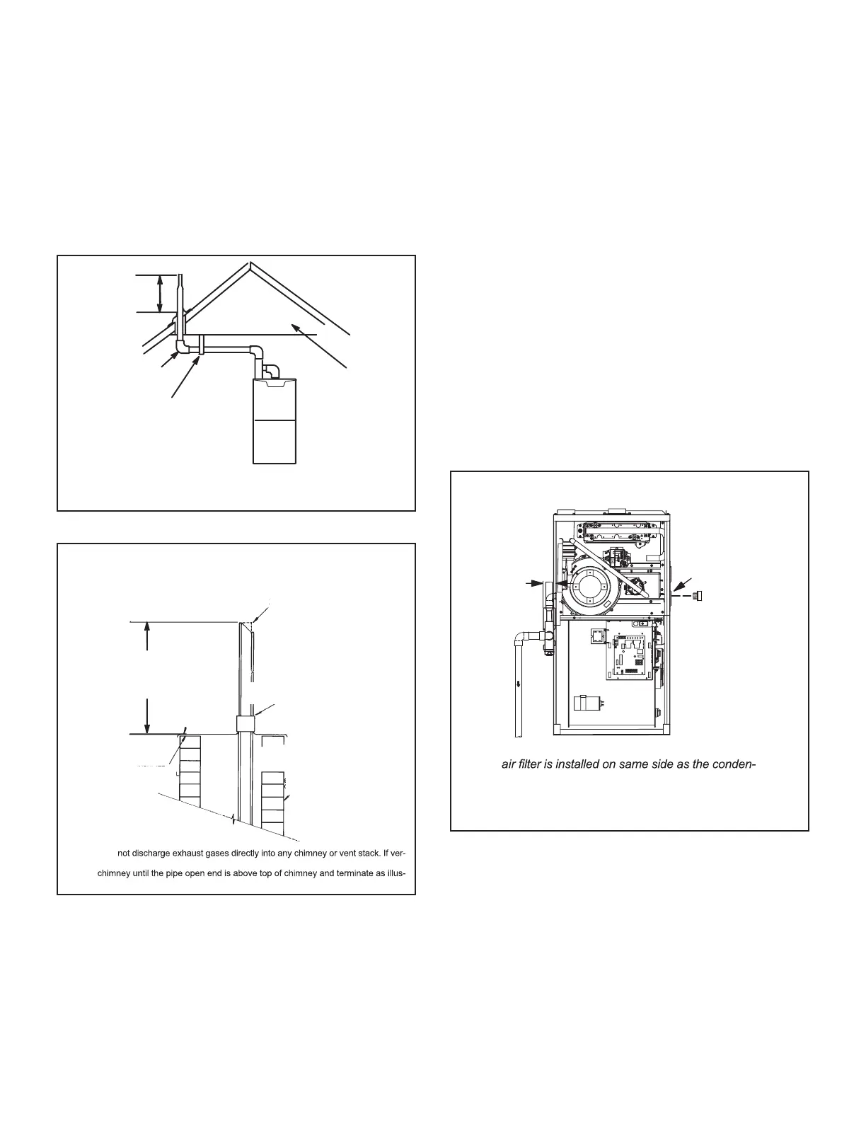
CONDENSATE TRAP AND PLUG LOCATIONS
(Unit shown in upflow position)
NOTE - In upflow applications where side return
sate trap, filter rack must be installed beyond
condensate trap or trap must be re-located to
avoid interference.
Trap
(same on
right side)
Plug
(same on left side)
1-1/2 in.
Rubber
Grommet
FIGURE 43
5 - FIGURE 46 and FIGURE 48 show the furnace and
evaporator coil using a separate drain. If necessary
the condensate line from the furnace and evaporator
coil can drain together. See FIGURE 47, FIGURE
49 and FIGURE 50 .
Upow furnace (FIGURE 49) - In upow furnace
applications the eld provided vent must be a
minimum 1” to a maximum 2” length above the
condensate drain outlet connection. Any length
above 2” may result in a ooded heat exchanger
if the combined primary drain line were to become
restricted.
 Loading...