Do you have a question about the Lennox EL297UH045XV36B and is the answer not in the manual?
Overview of the EL297UHV series gas furnaces, highlighting efficiency and features.
Detailed technical specifications for heating and cooling performance, including AFUE, input/output, and temperature rise.
Blower speed data for heating and cooling modes, including CFM ranges and motor power consumption.
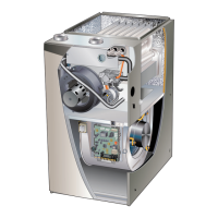
Diagram identifying key furnace components such as the heat exchanger, gas valve, and blower motor.
Details on control transformer, door interlock, circuit breaker, integrated control, and ESD safety.
Guide to setting DIP switches for thermostat selection and blower speed adjustments.
Explanation of diagnostic LEDs, push button operations, and various control modes.
Details on diagnostic codes, LED indicators, and control mode selection for the 103130-XX control.
Configuration settings for conventional thermostats, including heating and cooling blower adjustments.
Description of the blower drive, motor components, LED codes, and removal procedures.
Steps for safely powering up the unit and initiating blower motor start-up.
Guide for diagnosing and resolving issues related to motor operation and performance.
Procedure for testing motor winding resistance to diagnose faults.
Detailed descriptions of key heating components and their functions.
Steps for testing ignitor circuit resistance and supply voltage.
Details on the combustion air inducer, orifice sizes, and pressure switch function.
Procedure for testing pressure switch differentials using a manometer.
Requirements for approved piping materials, fittings, primer, and solvent cement.
Detailed steps for correctly preparing and cementing plastic pipe joints.
Guidelines for piping suspension, wall thickness, common vent removal, and termination.
Guidelines and safety precautions for vent termination, including clearance and material considerations.
Specifications for exhaust pipe routing, sizing, and horizontal offset requirements.
Guidelines for vent piping materials and system approvals.
A flowchart guide for determining the correct vent pipe size based on furnace capacity and installation factors.
Table showing maximum allowable vent lengths for standard terminations at lower altitudes.
Table showing maximum vent lengths for concentric terminations at lower altitudes.
Table showing maximum vent lengths for concentric terminations at higher altitudes.
Maximum allowable exhaust vent pipe lengths for standard terminations at lower altitudes.
Maximum allowable exhaust vent pipe lengths for standard terminations at higher altitudes.
Diagrams illustrating typical exhaust and intake pipe connections for upflow installations.
Diagrams illustrating typical exhaust and intake pipe connections for horizontal installations.
Instructions for installing intake piping in upflow non-direct vent applications.
Instructions for installing intake piping in horizontal non-direct vent applications.
Requirements for installing equipment in confined spaces, including attic and crawlspace.
Guidelines and safety precautions for vent termination, including clearance and material considerations.
Table showing maximum allowable exhaust vent pipe lengths without insulation in unconditioned spaces.
Diagram and table detailing required clearances for non-direct vent terminations in USA and Canada.
Diagram and table detailing required clearances for direct vent terminations in USA and Canada.
Guidelines for routing, separation, and support of direct vent intake and exhaust piping.
Details on field fabricated wall terminations, including straight and extended applications.
Alternative termination methods using tee and forty-five degree elbows.
Information on the flush-mount side wall termination kit for direct vent systems.
Information on concentric rooftop and wall termination kits for direct vent systems.
Guidelines for routing and supporting exhaust piping in non-direct vent applications.
Instructions for installing the condensate trap and drain assembly, including priming and routing.
Details on condensate trap installation with an optional overflow switch.
Configurations for draining condensate from furnaces with evaporator coils.
Detailed diagrams and instructions for assembling PVC condensate traps and drain lines.
Essential pre-start-up checks and procedures for initiating heating operation.
Steps for checking gas piping, supply pressure, and manifold pressure.
Procedures for ensuring proper combustion and operation at varying altitudes.
Testing procedures for verifying proper grounding and voltage supply to the integrated control.
Information on blower operation, temperature rise calculations, and external static pressure.
Routine maintenance tasks including filter inspection, pipe checks, and condensate trap care.
Step-by-step instructions for cleaning the furnace heat exchanger.
Procedure for cleaning the furnace burner assembly and inspecting for blockages.
Wiring diagram for the EL297UHV furnace ignition control (107045-XX).
Wiring diagram for the EL297UHV-135 furnace ignition control (103130-XX).
Wiring diagram illustrating the ignition control and blower drive connections.
Wiring diagram for the EL297UHV-135 ignition control and blower drive.
Flowchart detailing the heating sequence when using a two-stage thermostat.
Flowchart detailing the heating sequence when using a single-stage thermostat.
Wiring diagrams for connecting conventional and communicating thermostats to the furnace.
Wiring instructions for optional accessories like UV lights, HEPA filters, and ventilation controls.
Wiring details for various thermostat, indoor, and outdoor unit connections.
Guide to setting DIP switches for different heating stage thermostat configurations.
Guide to setting DIP switches for various heating stage thermostat configurations.
DIP switch settings and on-board link configurations for dual fuel heat pump systems.
Wiring diagrams for connecting communicating furnaces to outdoor units.
Wiring instructions for HEPA filters and ventilation control systems.
Wiring diagrams for furnace, indoor/outdoor units, and thermostats in communicating systems.
DIP switch settings for thermostat configurations involving 2-stage heating.
Procedure for programming the furnace control with the correct unit capacity size code.
Flowchart illustrating the heating sequence and potential troubleshooting points.
Continuation of the heating sequence flowchart, detailing second-stage operation.
Final part of the heating sequence flowchart, showing call for heat satisfaction.
Flowchart detailing the cooling sequence and potential troubleshooting points.
Flowchart illustrating the operation of the furnace in continuous fan mode.