EasyManua.ls Logo

Lennox EL297UH090XV60C User Manual

Lennox EL297UH090XV60C
115 pages
To Next Page IconTo Next Page
Page #1 background imageLoading...
Page #1 background image
Page 1
UNIT INFORMATIONUNIT INFORMATION
Service Literature
©2016 Lennox Industries, Inc.
WARNING
Improper installation, adjustment, alteration,
service or maintenance can cause property damage,
personal injury or loss of life. Installation and service
must be performed by a licensed professional HVAC
installer (or equivalent), service agency or the gas
supplier.
CAUTION
As with any mechanical equipment, contact with
sharp sheet metal edges can result in personal
injury. Take care while handling this equipment and
wear gloves and protective clothing.
EL297UHV(X) series units are 90% e󰀩ciency gas furnac-
es used for upow or horizontal applications only, man-
ufactured with Lennox Duralok heat exchangers formed
of aluminized steel. EL297UHV(X) units are available in
heating capacities of 44,000 to 132,000 Btuh and cooling
applications up to 5 tons. Refer to Product Specications
Manual for proper sizing.
Units are factory equipped for use with natural gas. Kits
are available for conversion to LPG operation. EL297UH-
V(X) model units are equipped with the icomfort
®
enabled
SureLight
®
two-stage variable speed integrated control.
EL297UHV(X) unit meets the California Nitrogen Oxides
(NOx) Standards and California Seasonal E󰀩ciency re-
quirements. All units use a redundant gas valve to assure
safety shut-o󰀨 as required by C.S.A.
All specications in this manual are subject to change.
Procedures outlined in this manual are presented as a
recommendation only and do not supersede or replace lo-
cal or state codes. In the absence of local or state codes,
the guidelines and procedures outlined in this manual (ex-
cept where noted) are recommendations only and do not
constitute code.
TABLE OF CONTENTS
Specications . . . . . . . . . . . . . . . . . . . . . . . . . . . . . Page 2
Blower CFM Data . . . . . . . . . . . . . . . . . . . . . . . . . Page 5
I Unit Components . . . . . . . . . . . . . . . . . . . . . . . Page 26
II Installation . . . . . . . . . . . . . . . . . . . . . . . . . . . . . Page 57
III Start Up . . . . . . . . . . . . . . . . . . . . . . . . . . . . . . Page 79
IV Heating System Service Checks . . . . . . . . . Page 80
V Typical Operating Characteristics . . . . . . . . . Page 83
VI Maintenance . . . . . . . . . . . . . . . . . . . . . . . . . . Page 83
VII Wiring and Sequence of Operation . . . . . . Page 86
Program Unit Capacity Size Mode . . . . . . . Page 110
Troubleshooting . . . . . . . . . . . . . . . . . . . . . . . . Page 111
EL297UHV(X)
100088
Communicating-ENABLED EL297UHV SERIES UNITS
Question and Answer IconNeed help?

Do you have a question about the Lennox EL297UH090XV60C and is the answer not in the manual?

Lennox EL297UH090XV60C Specifications

General IconGeneral
BrandLennox
ModelEL297UH090XV60C
CategoryFurnace
LanguageEnglish

Summary

SPECIFICATIONS

Gas Heating Performance

Details heating input, output, and temperature rise for various models.

BLOWER DATA

HEATING

Presents heating speed CFM data based on DIP switch settings.

COOLING

Details cooling speed CFM data based on DIP switch settings.

I-UNIT COMPONENTS

A- Control Box

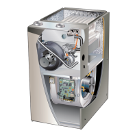
Describes components within the control box like transformer and breaker.

5. Integrated Control (A92)

Details the communicating control system for ignition and blower operation.

Two Stage Operation / Thermostat Selection DIP Switch

Ignition Control Diagnostic Modes

Diagnostic LED

Explains the function of the seven-segment diagnostic LED.

Diagnostic Push Button

Describes how to use the push button for accessing diagnostic modes.

Error Code Recall Mode

Procedure for accessing and clearing error codes.

Flame Signal Mode

How to access and interpret flame signal readings.

Program Unit Capacity/Size Mode

Steps to set the furnace model and capacity code.

Soft Disable

Explains soft disable status and troubleshooting steps.

Integrated Control DIP Switch Settings

B- Indoor Blower Motor

Blower Drive

Information on the ECM motor, its LED codes, and replacement.

Initial Power Up

Troubleshooting Motor Operation

Steps to verify motor operation using a test meter.

Troubleshooting Motor Windings

TEST A

Procedure to check motor winding resistance to ground.

TEST B

Procedure to measure phase-to-phase resistance of motor windings.

C- Heating Components

1. Ignitor

Details the SureLight ignitor, its voltage, and resistance values.

2. Flame Sensor

Explains the flame sensor location, function, and signal check.

3. Gas Valve

Information on the redundant gas valve and its connections.

4. Flame Rollout Switches (S47)

Describes the high-temperature limit switches for safety.

6. Primary Limit Control (S10)

Explains the primary limit switch in the heat exchanger.

Ignitor Check

Test 1

Checks ignitor circuit resistance across terminals 1 and 5.

Test 2

Checks ignitor resistance at the 2-pin plug near the manifold.

Test 3

Measures ignitor voltage during the warm-up period.

Combustion Air Inducer

8. Combustion Air Inducer Pressure Switch (S18)

Explains the dual-stage pressure switch function.

Pressure Switch Check

II-PLACEMENT AND INSTALLATION

Venting Practices

III-START-UP

B-Heating Start-Up

Procedure for safely starting the furnace heating sequence.

Gas Valve Operation

Instructions for operating the gas valve and safety precautions.

Failure To Operate

Troubleshooting guide for common operational failures.

IV-HEATING SYSTEM SERVICE CHECKS

B-Gas Piping

Guidelines for gas piping installation and safety.

C-Testing Gas Piping

Procedures for testing gas piping for leaks and pressure.

G- Proper Combustion

I- Proper Ground and Voltage

V-TYPICAL OPERATING CHARACTERISTICS

VI-MAINTENANCE

VII- Wiring and Sequence of Operation

Electronic Ignition

VIII- FIELD WIRING WITH CONVENTIONAL AND COMMUNICATING ENABLED THERMOSTAT

Ignition Control DIP Switch Settings and On Board Links

IX- Program Unit Capacity Size Modes

X- Troubleshooting

Troubleshooting: Heating Sequence of Operation

Flowchart detailing the furnace heating operation sequence.

Related product manuals