Page 7
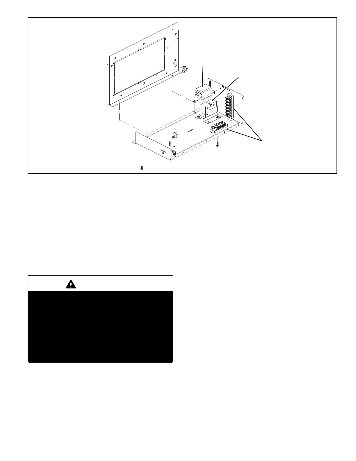
FIGURE 2
CBA27UHE CONTROL BOX
BLOWER RELAY
(K20)
TRANSFORMER
(T1)
TERMINAL STRIP
(TB1)
I-APPLICATION
All major blower coil components must be matched ac
cording to Lennox recommendations for the unit to be
covered under warranty. Refer to the Product Specifications
(EHB) for approved system matchups. A misapplied system
will cause erratic operation and can result in early unit failure.
The units come with factory installed check / expansion valve
for all applications. The TXV valve has been installed internally
for a cleaner installation and is accessible if required.
ELECTROSTATIC DISCHARGE (ESD)
Precautions and Procedures
CAUTION
Electrostatic discharge can affect electronic
components. Take precautions during unit instal
lation and service to protect the unit's electronic
controls. Precautions will help to avoid control
exposure to electrostatic discharge by putting
the unit, the control and the technician at the
same electrostatic potential. Neutralize electro
static charge by touching hand and all tools on an
unpainted unit surface before performing any
service procedure.
II-UNIT COMPONENTS
A-Control Box
See figure 2 for CBA27UHE control box. Line voltage and
electric heat connections are made in the control box. Op
tional electric heat fits through an opening located in the
center of the control box. When electric heat is not used,
knock out plates cover the opening. The electric heat control
arrangement is detailed in the electric heat section of this
manual.
B-Terminal Strip (TB1)
CBA27UHE units are equipped with a low voltage terminal
strip (TB1) located in the control box. See figure 2. The strip
is used for making up all indoor thermostat wires. The out
door unit low voltage wiring connections to TB1 may be
spliced with wire nuts inside the CB units.
Y1 to Y2 Jumper
A factory installed jumper will be installed between “Y1 and
“Y2” for single-stage stage cooling. Remove the jumper for
two-stage cooling.
R to W2 Jumper
A factory installed jumper will be installed between “R“ and
“W2” for single-stage heat pump applications. Remove the
jumper for two-stage non-heat-pump application.
 Loading...