EasyManua.ls Logo

Lennox CB26UH User Manual

Lennox CB26UH
15 pages
To Next Page IconTo Next Page
Page #1 background imageLoading...
Page #1 background image
Page 1
© 2005 Lennox Industries Inc.
Litho U.S.A.
Corp. 0527−L10
CB26UH
CBX26UH
Service Literature
CB26UH &CBX26UH Series
The CB26UH, and CBX26UH are high efficiency blower coils.
Several models are available in sizes ranging from 1-1/2
through 5 tons (5.3 through 17.6 kW). The CBX26UH is de-
signed for R−410A refrigerant and the CB26UH is designed for
R−22 refrigerant. The units are up flow / horizontal that can be
field converted to down flow applications. The units come with
a factory installed check and expansion valve for cooling or
heat pump applications.
CB26UH and CBX26UH series units are designed to be
matched with the 13SEER air conditioner and heat pump line,
but can be matched with other air conditioners or heat pumps
as noted in the rating information. See Engineering Handbook.
Electric heat, in several kW sizes, can be field installed in the
CB26UH and CBX26UH cabinets.
Information contained in this manual is intended for use by ex-
perienced HVAC service technicians only. All specifications are
subject to change. Procedures outlined in this manual are pre-
sented as a recommendation only and do not supersede or re-
place local or state codes.
IMPORTANT
Improper installation, adjustment, alteration, service
or maintenance can cause property damage, person-
al injury or loss of life. Installation and service must
be performed by a qualified installer or service
agency.
WARNING
Electric shock hazard. Can cause injury
or death. Before attempting to perform
any service or maintenance, turn the
electrical power to unit OFF at discon-
nect switch(es). Unit may have multiple
power supplies.
Table of Contents
Specifications / Electrical Data NO TAG. . . . . .
Blower Data Page 3. . . . . . . . . . . . . . . . . . . . . .
I Application Page 4. . . . . . . . . . . . . . . . . . . . . .
II Unit Components Page 5. . . . . . . . . . . . . . . .
III Optional Electric Heat Page 6. . . . . . . . . . .
IV Configuration Modification Page 10. . . . . . .
V Start Up Page 13. . . . . . . . . . . . . . . . . . . . . . . .
VI Typical Operating Characteristics Page 14.
VII Maintenance Page 14. . . . . . . . . . . . . . . . . . .
VIII Wiring Diagrams Page 15. . . . . . . . . . . . . . .
Question and Answer IconNeed help?

Do you have a question about the Lennox CB26UH and is the answer not in the manual?

Lennox CB26UH Specifications

General IconGeneral
ModelCB26UH
TypeBlower
Voltage115/208-230
Phase1
Motor TypePSC
Horsepower1/3 HP
Blower Wheel TypeCentrifugal
Housing MaterialSteel
Mounting TypeFloor

Summary

Unit Information and Safety

Important Safety Warnings

Critical warnings on improper installation, adjustment, alteration, service, or maintenance.

Electrical Shock Hazard Warning

Alerts to electric shock risk and necessity of power disconnection before service.

Specifications and Accessories

Optional Accessories List

Lists available optional accessories for the CB26UH and CBX26UH series units.

Blower Performance Data Tables

Application and ESD Precautions

Unit Application Requirements

Details component matching and system matchup requirements for warranty and performance.

Electrostatic Discharge (ESD) Safety

Provides guidance on preventing ESD damage to electronic components during handling.

Unit Components Description

Control Box and Transformer Details

Describes the control box, its wiring, and the 24VAC transformer's role.

Blower Motor, Coil, and Drain Pans

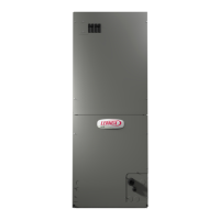
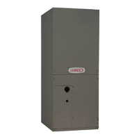
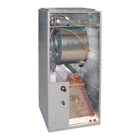
Details the blower motor assembly, capacitor, dual slab coil, and plastic drain pans.

Optional Electric Heat System Details

Electric Heat Matchups and Ratings

Lists approved electric heat matchups and their electrical ratings.

Electric Heat Components and Operation

Explains sequencer relays, limits, circuit breakers, and heating elements.

Electric Heat Specifications Table 2

Electric Heat Specifications Table 3

Electric Heat Specifications Table 4

Configuration Modifications and Installation

General Installation Warnings

Critical warnings regarding proper unit installation and service procedures.

Upflow and Horizontal Installation

Details procedures for upflow and horizontal air discharge installations.

Horizontal Discharge Modification Procedures

Suspending Horizontal Unit

Instructions for properly supporting the unit during horizontal installation.

Right-Hand Discharge Modification

Step-by-step guide for converting to a right-hand air discharge configuration.

Condensate Drain Installation and Testing

Drain Line Connections and Traps

Covers drain line connections, trap requirements, and sealant use.

Testing the Condensate Drain System

Outlines the process for testing drain pan and line function post-installation.

Unit Start-Up and Operation

Preliminary Checks and Shutdowns

Covers pre-startup checks, safety, and extended shutdown procedures.

Cooling and Heating Start-Up

Provides generalized procedures for initiating cooling and heating modes.

Operating Characteristics and Maintenance

Blower Operation and Static Pressure

Details blower adjustment, static pressure measurement, and speed tap changes.

Maintenance Procedures

Covers filter inspection, blower cleaning, and electrical system checks.

Wiring Diagrams and Sequence of Operations

Electrical Wiring Diagram

Illustrates key electrical components and connections within the unit.

Sequence of Operation Details

Details the operational steps for heating stages and cooling mode.

Related product manuals