EasyManua.ls Logo

Lennox CBA27UHE-030 User Manual

Lennox CBA27UHE-030
45 pages
To Next Page IconTo Next Page
Page #1 background imageLoading...
Page #1 background image
Page 1
2017 Lennox Industries Inc.
Corp. 1701-L3
Service Literature
May 2017
CBA27UHE
Elite
®
Series CBA27UHE Units
IT IS HIGHLY RECOMMENDED IF THE AIR HANDLER IS INSTALLED IN A
UNCONDITIONED SPACE THAT A CIRCUIT BREAKER COVER (ORDERED
SEPARATELY) IS USED. ORDER LENNOX CATALOG # 82W01.
CIRCUIT BREAKER
OPENING
CIRCUIT BREAKER
COVER
WARNING
Improper installation, adjustment, alteration, service or
maintenance can cause personal injury, loss of life, or
damage to property.
Installation and service must be performed by a licensed
professional installer (or equivalent) or a service agency.
CAUTION
As with any mechanical equipment, contact with sharp
sheet metal edges can result in personal injury. Take care
while handling this equipment and wear gloves and pro
tective clothing.
Table of Contents
Specifications / Electrical Data Page 2......
Blower Data Page 4......................
Parts Arrangement Page 6................
I Application Page 7......................
II Unit Components Page 7................
III Optional Electric Heat Page 9...........
IV Start Up Page 28.......................
V Typical Operating Characteristics Page 28..
VI Maintenance Page 29...................
VII Wiring Diagrams and Sequence
of Operations Page 32..................
The Elite CBA27UHE units are high efficiency blower coils
featuring an all-aluminum coil. Several models are avail
able in sizes ranging from 1‐1/2 through 5 tons (5.3 through
17.6 kW). The CBA27UHE is an upflow horizontal unit de
signed for HCFC-410A refrigerant. See unit installation in
structions for more detail. A kit is available for downflow ap
plications. CBA27UHE units come with a factory-installed
check / expansion valve for cooling or heat pump applica
tions.
CBA27UHE series units are designed to be matched with 14
SEER air conditioner or heat pump units. While these blower
coil units are designed to be primarily matched with these out
door units, they may be matched with other air conditioners or
heat pumps as noted in the rating information.
ECB29 electric heat, in several voltages and kW sizes, can be
field installed in the CBA27UHE cabinets.
Information contained in this manual is intended for use by ex
perienced HVAC service technicians only. All specifications are
subject to change. Procedures outlined in this manual are pre
sented as a recommendation only and do not supersede or re
place local or state codes.
IMPORTANT: Special procedures are required for clean
ing the aluminum coil in this unit. See page 29 in this manual
for information.

Other manuals for Lennox CBA27UHE-030

Question and Answer IconNeed help?

Do you have a question about the Lennox CBA27UHE-030 and is the answer not in the manual?

Lennox CBA27UHE-030 Specifications

General IconGeneral
BrandLennox
ModelCBA27UHE-030
CategoryBlower
LanguageEnglish

Summary

Elite Series CBA27UHE Units

Safety Information

Critical safety warnings and precautions for installation and handling.

Unit Overview

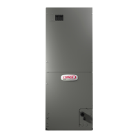
General introduction to the CBA27UHE high efficiency blower coils.

Specifications

General Data

Covers tonnage, connections, coil, and blower dimensions.

Electrical Data

Details voltage, circuit ampacity, and overcurrent protection.

Blower Data

Blower Performance Tables

Presents CFM and Watts data for various static pressures and taps.

Replacement Circuit Breakers

Lists catalog numbers for replacement circuit breakers.

Parts Arrangement

Figure 1 Diagram

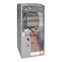
Illustrates the physical layout of unit components.

Unit Components and Application

Application Requirements

Emphasizes matching components for warranty and performance.

Control Box and Terminal Strip

Details the control box, terminal strip, and jumpers for cooling stages.

Electrostatic Discharge (ESD) Precautions

Procedures to prevent damage to electronic components from static discharge.

Key Unit Components

Transformer, Fuse, and Relays

Explains the function of the control transformer, fuse, blower relay, and dehumidification relay.

Blower Motor (B3)

Describes the blower motor features, balancing, and important notes.

Optional Electric Heat

Matchups and Ratings

Refers to data for approved electric heat matchups and electrical ratings.

Electric Heat Components

Details sequencer relays and temperature limits for electric heat sections.

208/230 Volt Electric Heat Sections

Specific information on temperature limits and their operation in 208/230V sections.

Electric Heat Data Tables

Heat Data for CBA27UHE-018

Detailed electrical specifications for electric heat options for the -018 model.

Heat Data for CBA27UHE-036

Detailed electrical specifications for electric heat options for the -036 model.

Heat Data for CBA27UHE-048

Detailed electrical specifications for electric heat options for the -048 model.

Heat Data for CBA27UHE-060

Detailed electrical specifications for electric heat options for the -060 model.

Start-Up and Operation

Preliminary and Seasonal Checks

Essential pre-start checks for proper installation and safety.

Cooling Start-Up Procedure

Steps for initiating cooling operation, including refrigerant charge.

Heating Start-Up Procedure

Steps for initiating heating operation and blower staging.

Safety and Shutdown Procedures

Instructions for emergency shutdown and extended period shutdown.

Typical Operating Characteristics

Blower Operation and Adjustment

How blower operation is controlled and adjusted via thermostat settings.

External Static Pressure Measurement

Procedure for measuring and ensuring acceptable external static pressure.

Blower Speed Tap Settings

Guide to selecting blower speed taps for different operating conditions.

Maintenance

Filter Inspection and Replacement

Guidelines for maintaining air filters to ensure proper airflow and unit performance.

Coil Cleaning Precautions

Important notes on cleaning aluminum coils to prevent damage from chemical solutions.

Supply Air Blower Maintenance

Instructions for checking and maintaining the supply air blower assembly.

Electrical System Checks

Procedures for checking electrical connections, breakers, and voltage.

Blower Motor (ECM) Information

Details on the ECM blower motor, its removal, and handling.

ECM Blower Motor Operation

Constant Torque Control

Explains how ECM maintains torque under varying static pressures.

Voltage Connections and Installation

Recommended wiring practices and connector orientation for ECM installation.

Blower Motor Troubleshooting

Checking 230VAC Voltage Input

Procedure for verifying high voltage supply to the blower motor.

Low-Voltage Communication Input Check

Steps to diagnose low-voltage communication issues affecting motor operation.

Wiring Diagrams and Sequence of Operations

Unit Sequence of Operation

Describes operational sequences for heating and cooling modes.

Blower Speed Tap Settings Chart

Provides recommended blower speed tap selections based on operating conditions.

Field Wiring Connections

Units Without Circuit Breakers

Wiring diagrams for units that do not use circuit breakers for electric heat.

Units With Circuit Breakers

Wiring diagrams for units that utilize circuit breakers for electric heat.

Electric Heat Sequence of Operation: ECB29-2.5 to -6CB

First Stage Heat Sequence

Operational steps for the first stage of electric heat for specific models.

Second Stage Heat Sequence

Operational steps for the second stage of electric heat for specific models.

Electric Heat Sequence of Operation: ECB29-8, 8CB

Heating-Electric Sequence

Operational flow for electric heat components in ECB29-8 and 8CB series.

Electric Heat Sequence of Operation: ECB29-9CB, 10, 10CB

First Stage Heat Sequence

Operational steps for the first stage of electric heat for specific models.

Second Stage Heat Sequence

Operational steps for the second stage of electric heat for specific models.

Electric Heat Sequence of Operation: ECB29-12.5CB, -15CB

First Stage Heat Sequence

Operational steps for the first stage of electric heat for specific models.

Second Stage Heat Sequence

Operational steps for the second stage of electric heat for specific models.

Electric Heat Sequence of Operation: ECB29-20CB

First Stage Heat Sequence

Operational steps for the first stage of electric heat for specific models.

Second Stage Heat Sequence

Operational steps for the second stage of electric heat for specific models.

Electric Heat Sequence of Operation: ECB29-25CB

First Stage Heat Sequence

Operational steps for the first stage of electric heat for specific models.

Second Stage Heat Sequence

Operational steps for the second stage of electric heat for specific models.

Third Stage Heat Sequence

Operational steps for the third stage of electric heat for specific models.

Electric Heat Sequence of Operation: ECB29-8, -10 THREE PHASE

Heating-Electric Sequence

Operational flow for electric heat components in three-phase models.

Electric Heat Sequence of Operation: ECB29-15CB THREE PHASE

Heating-Electric Sequence

Operational flow for electric heat components in three-phase models.

Electric Heat Sequence of Operation: ECB29-20CB, -25CB THREE PHASE

First Stage Heat Sequence

Operational steps for the first stage of electric heat in three-phase models.

Second Stage Heat Sequence

Operational steps for the second stage of electric heat in three-phase models.

Electric Heat Sequence of Operation: ECB29-10, -15, -20, -25CB 460V THREE PHASE

First Stage Heat Sequence

Operational steps for the first stage of electric heat in 460V three-phase models.

Second Stage Heat Sequence

Operational steps for the second stage of electric heat in 460V three-phase models.

Dehumidification Relay K183

Operation Sequence

Explains the function and sequence of the K183 dehumidification relay.

Blower Speed Tap Selection

Guide on selecting blower speed taps for system configurations.

Single Stage Systems

Specific blower speed tap configurations for single-stage systems.

Two Stage Systems

Specific blower speed tap configurations for two-stage systems.

K183 Dehumidification Relay Wiring Harness

Wiring Diagram

Schematic illustration of the K183 relay and its connections.

Related product manuals