Page 10
506101−01 07/09
WARNING
When using a high pressure gas such
as dry nitrogen to pressurize a
refrigeration or air conditioning
system, use a regulator that can
control the pressure down to 1 or 2
psig (6.9 to 13.8 kPa).
CAUTION
Brazing alloys and flux contain materials which are
hazardous to your health.
Avoid breathing vapors or fumes from brazing
operations. Perform operations only in well
ventilated areas.
Wear gloves and protective goggles or face shield
to protect against burns.
Wash hands with soap and water after handling
brazing alloys and flux.
WARNING
Danger of fire. Bleeding the
refrigerant charge from only the high
side may result in the low side shell
and suction tubing being
pressurized. Application of a brazing
torch while pressurized may result in
ignition of the refrigerant and oil
mixture − check the high and low
pressures before unbrazing.
2. Remove service cap and core from both the suction
and liquid line service ports.
3. Connect gauge low pressure side to liquid line service
valve.
4. To protect components during brazing, wrap a wet
cloth around the liquid line service valve body and
copper tube stub and use another wet cloth
underneath the valve body to protect the base paint.
Also, shield the light maroon R−410A sticker.
5. Flow regulated nitrogen (at 1 to 2 psig) through the
refrigeration gauge set into the valve stem port
connection on the liquid line service valve and out of
the valve stem port connection on the suction service
valve.
NOTE − The fixed orifice or TXV metering device at the
indoor unit will allow low pressure nitrogen to flow through
the system.)
NOTE − Use silver alloy brazing rods with five or six percent
minimum silver alloy for copper−to−copper brazing or 45
percent silver alloy for copper−to−brass or copper−to−steel
brazing.
6. Braze the liquid line to the liquid line service valve.
Turn off nitrogen flow.
IMPORTANT
Repeat procedure starting at paragraph 4 for brazing the
suction line to service port valve.
7. After all connections have been brazed, disconnect
manifold gauge set the from service ports and remove
wrapping. Reinstall the service port core for both of the
outdoor unit’s service valves.
Removing Indoor Unit Metering Device
Remove the existing HCFC−22 fixed orifice or TXV from
the indoor coil. The existing indoor unit HCFC−22 metering
device is not approved for use with HFC−410A refrigerant
and may prevent proper flushing.
REPLACEMENT PARTS
If replacement parts are necessary for the indoor unit,
order kit 69J46 (LB−95325A). The kit includes:
TEFLON RINGS (20)
BRASS NUTS (10)
LIQUID LINE ASSEMBLIES
(INCLUDES STRAINER) (10)
LIQUID LINE ORIFICE HOUSINGS (10)
LIQUID LINE
ASSEMBLY
COPPER
TUBE
PISTON
RETAINER
STRAINER
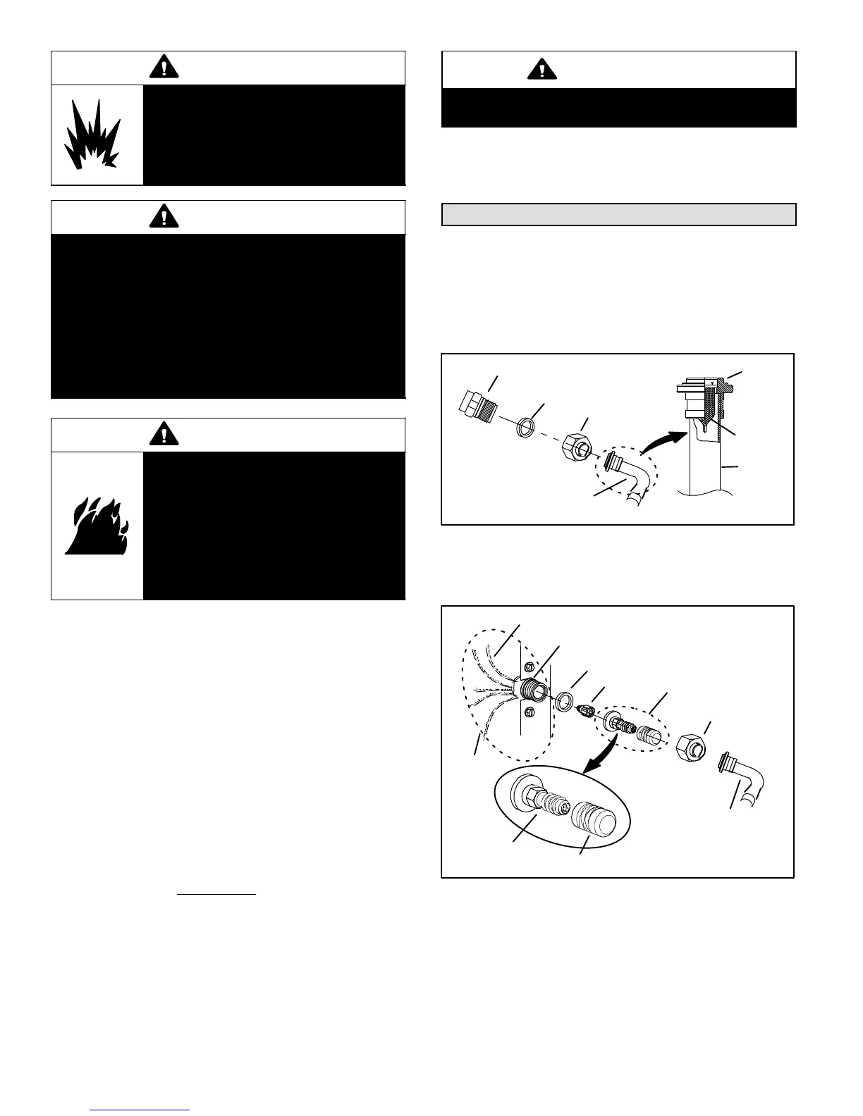
Figure 18. 69J46 Kit Components
TYPICAL FIXED ORIFICE REMOVAL PROCEDURE
Use the following procedures to remove a fixed orifice
metering device from an existing indoor unit:
TEFLON RING
REMOVE AND DISCARD
VALVE STEM ASSEMBLY
(IF PRESENT)
FIXED
ORIFICE
(Uncased Coil Shown)
VALVE STEM
VALVE STEM CAP
BRASS NUT
LIQUID LINE ASSEMBLY
(INCLUDES STRAINER)
LIQUID LINE ORIFICE HOUSING
DISTRIBUTOR TUBES
DISTRIBUTOR
ASSEMBLY
Figure 19. Typical Fixed Orifice Removal
1. On fully cased coils, remove the coil access and
plumbing panels.
2. Remove any shipping clamps holding the liquid line
and distributor assembly.
3. Using two wrenches, disconnect liquid line from liquid
line orifice housing. Take care not to twist or damage
distributor tubes during this process.

 Loading...