Page 24
B-ELS120S4D, 150
ELS-120,150-G,J,M,Y
537904-01
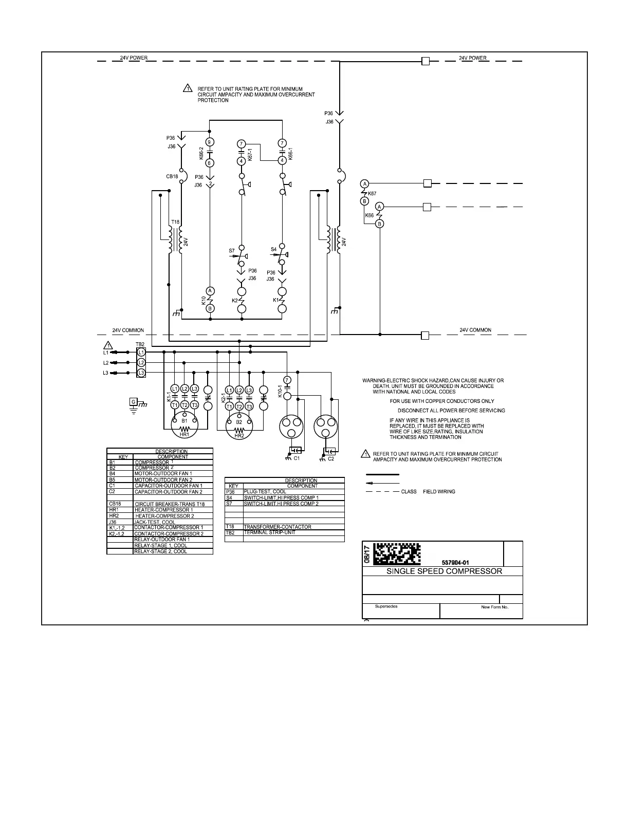
K66,-1,2
K67,-1,2
DENOTES OPTIONAL COMPONENTS
LINE VOLTAGE FIELD INSTALLED
C
4
R
TB14
TB14
K10,-1
TB14
TERMINAL STRIP-CLASS II VOLTAGE
CB8
CIRCUIT BREAKER-TRANS T1
S24
S25
T1
SWITCH-LOSS OF CHARGE,COMP 1
SWITCH-LOSS OF CHARGE,COMP 2
TRANSFORMER-CONTROL
SECTION A 3
WIRING DIAGRAM
4
S25
S24
3
1
CB8
T1
208V
COOL 1
COOL 2
C2
C1
208V
2
2
1
3
1
3
B4
B5
K2-2
6
08/17
400V
240 / 460 / 575V
400V
240 / 460 / 575V
K1-2
REV. 0
II
First Stage Cool
1 - Cooling demand energizes K66 relay coil at
thermostat terminal Y1.
2 - K66-1 contacts close, voltage passes through S24
loss of charge switch and high pressure switch S4,
energizing compressor contactor K1.
3 - At the same time, K66-2 contacts close, energizing
outdoor fan relay K10.
4 - K1-1 closes, energizing compressor B1. K10-1
closes energizing outdoor fans B4 and B5. K1-2
opens to de-energize crankcase heater HR1.
Second Stage Cool
5 - Cooling demand energizes K67 relay coil at
thermostat terminal Y2.
6 - K67-1 contacts close, voltage passes through S25
loss of charge switch and S7 high pressure switch
energizing compressor contactor K2.
7 - K2-1 closes energizing compressor B2. K2-2 opens
to de-energize crankcase heater HR2.
 Loading...