IOM / ROOF-TOP FLEXY™ Series - Page 25
1
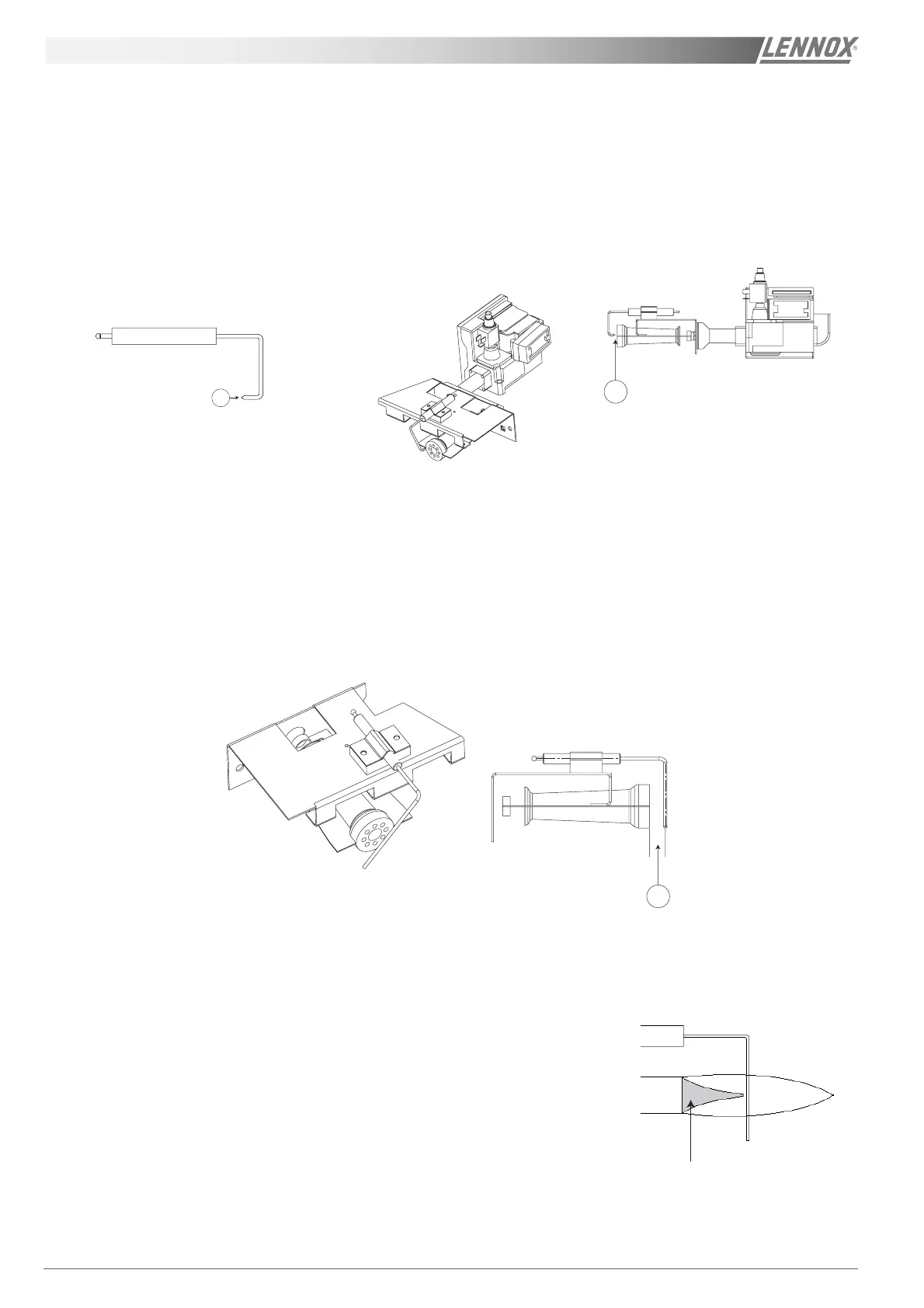
IGNITION ELECTRODE
The following two checks can be made :
- Ensure that the electrode tip (1 – Figure 25) is always sharp and oxide-free. Use some sand paper to
clean it, if necessary.
- The space between the tip and the air duct must be 3 mm approx. (2 – Figure 26).
IONISATION SENSOR
- The sensor must be placed in the air duct at approximately 12.5 mm from the burner (3 – Figure 27).
Check that the position is correct in the flame (see Figure 28).
It must be placed just after the flame front.
There is no ionisation inside the blue cone. It reduces and reaches the end of
the flame afterwards.
2
3
GAS BURNERGAS BURNER
GAS BURNERGAS BURNER
GAS BURNER
Figure 25
Figure 26
Figure 27
Cône bleu
Figure 28
 Loading...