Page 10
5–SureLight Ignitor
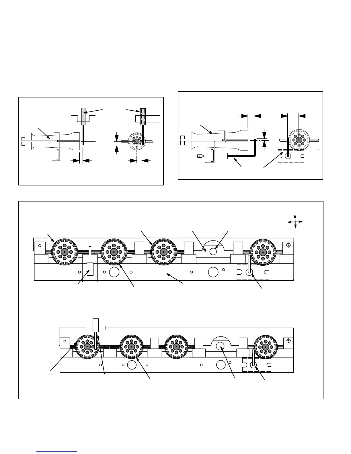
Figure 12 and 14 shows the position of the SureLight
hot surface ignitor in perspective with the rest of the
burner assembly. The hot surface ignitor lights the two
rightmost burners and the burners cross-light to the left. A
flame retention ring in the end of each burner is used to
maintain correct flame length and shape and to keep the
flame from lifting off the burner head. The hot surface
ignitor is rated at 1800_F (982_C) in 17 seconds with a
120VAC 4 amp power source.
FIGURE 12
BURNER
IGNITOR LOCATION
SIDE VIEW END VIEW
0.26 in. (7 mm)
0.06 in. (1.5 mm)
0.47 in. (12 mm)
0.04 in. (1 mm)
0.26 in. (7 mm)
0.06 in.
(1.5 mm)
IGNITOR
6–Flame Sensor
Figure 14 shows the position of the flame sensor in per-
spective with the rest of the burner assembly. The
flame sensor uses flame rectification to sense com-
bustion. Figure 13 shows the gap between tip of the
electrode and the burner surface.
FLAME SENSOR TO BURNER GAP
BURNER
FLAME
SENSOR
SIDE VIEW END VIEW
1/4 in. 7 mm
1/32 in. 0.79 mm
3/16 in.
4.7 mm
11/16 in. 18 mm
1/32 in. 0.79 mm
FIGURE 13
BURNER
FLAME RETENTION RING
UPPER BURNER
MOUNTING RAIL
LOWER BURNER
MOUNTING RAIL
MANIFOLD ORIFICE
Right Left
Top
Bottom
FLAME SENSOR
SURELIGHT IGNITOR
SureLight Ignitor and Sensor Location
(Early Models, Ignitor On Bottom)
FLAME SENSOR
FLAME RETENTION RING
UPPER BURNER
MOUNTING
RAIL
ORIFICE
SURELIGHT
IGNITOR
SureLight Ignitor and Sensor Location
(Late Models, Ignitor On Top)
FIGURE 14
 Loading...


