Page 9
C–Heating Components (Figures 8 and 9 )
Heating components are located inside the front louvered
panel. Inside the heating compartment are the combus-
tion air blower (B6), flame rollout switches (S47), primary
limit control (S10), ignitor, flame sensor, gas valve (GV1),
and the combustion air blower prove switches (S18 and
S102).
1–Combustion Air Blower (B6)
All G27M units use a two–stage combustion air blower to
move air through the burners and heat exchanger during
heating operation. The blower uses a 120VAC motor. The
motor operates during all heating operation and is con-
trolled by the SureLight integrated control A3. The blower
operates for 15 seconds before burner ignition (pre-
purge) and for 5 seconds after the gas valve closes (post-
purge). The combustion air blower operates on low speed
during first–stage heat (low fire), then switches to high
speed for second–stage heat (high fire).
2–Flame Rollout Switches (S47)
Flame rollout switch is a high temperature limit switch
located on top of the burner box (see figure 11). Each
furnace is equipped with two identical switches. One
switch is located over the leftmost burner and the other
switch is located over the rightmost burner. The switch is
a N.C. SPST manual-reset switch which opens at 260_F +
12_F (126.7_C + 6.7_C) on a temperature rise. The switch
is factory set and cannot be adjusted. To manually reset
a tripped switch, push the reset button located on the
control. The switches are connected in series and moni-
tored by the SureLight control A3. When S47 senses
rollout, the control immediately stops ignition and
closes the gas valve. If unit is running and flame rollout
is detected, the gas valve will close and ignition control
will be disabled. Rollout can be caused by a restricted
heat exchanger or a blocked flue.
FIGURE 10
ROLLOUT SWITCH (S47)
MANUAL
RESET BUTTON
3–Primary Limit Control (S10)
The primary limit (S10) is located in the middle of the
heating vestibule panel (see figure 9). S10 is the same
type of limit as (1) S21 or (2) S21 as shown in figure 7.
G27M–60 and –75 units use the same type limit as (1) S21.
G27M–100 and –120 units use the same type limit as (2)
S21. When excess heat is sensed in the heat exchanger,
the limit will open. If the limit is tripped, the SureLight
control energizes the supply air blower and closes the
gas valve. The limit automatically resets when unit
temperature returns to normal. The switch is factory set
and cannot be adjusted. The switch has different set-
points for each unit model number. However, the set
point will be printed on the side of the limit.
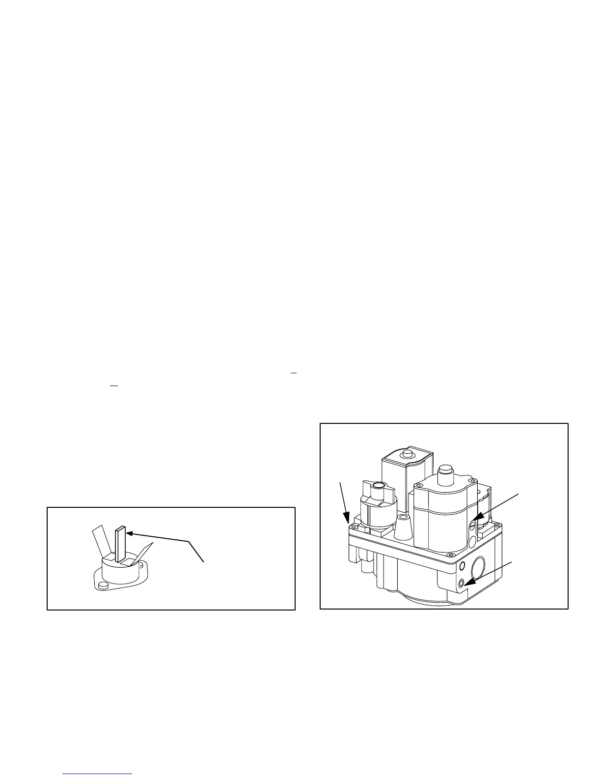
4–Gas Valve (GV1)
The G27M uses a gas valve manufactured by White
Rodgers. The valve is a two-stage internally redundant
to assure safety shut–off. If the gas valve must be re-
placed, the same type valve must be used.
24VAC terminals and gas control knob are located on top
of the valve. All terminals on the gas valve are connected
to wires from the SureLight integrated control. 24V ap-
plied to the terminals energizes the valve.
Inlet and outlet pressure taps are located on the valve. A
regulator adjustment screw is located on the side of the
valve. Refer to figure 11 for location of valve features.
NOTE–Do not attempt to regulate low fire manifold
pressure.
FIGURE 11
HIGH FIRE
MANIFOLD
PRESSURE
ADJUSTMENT
MANIFOLD
PRESSURE
OUTLET
WHITE RODGERS 36E SERIES GAS VALVE
INLET
PRESSURE
 Loading...


