Page 7
indoor blower (B3) operating on low speed. After a set
time delay the unit switches to second–stage heat (high
fire). The combustion air blower and indoor blower
also switch to second–stage heat mode.
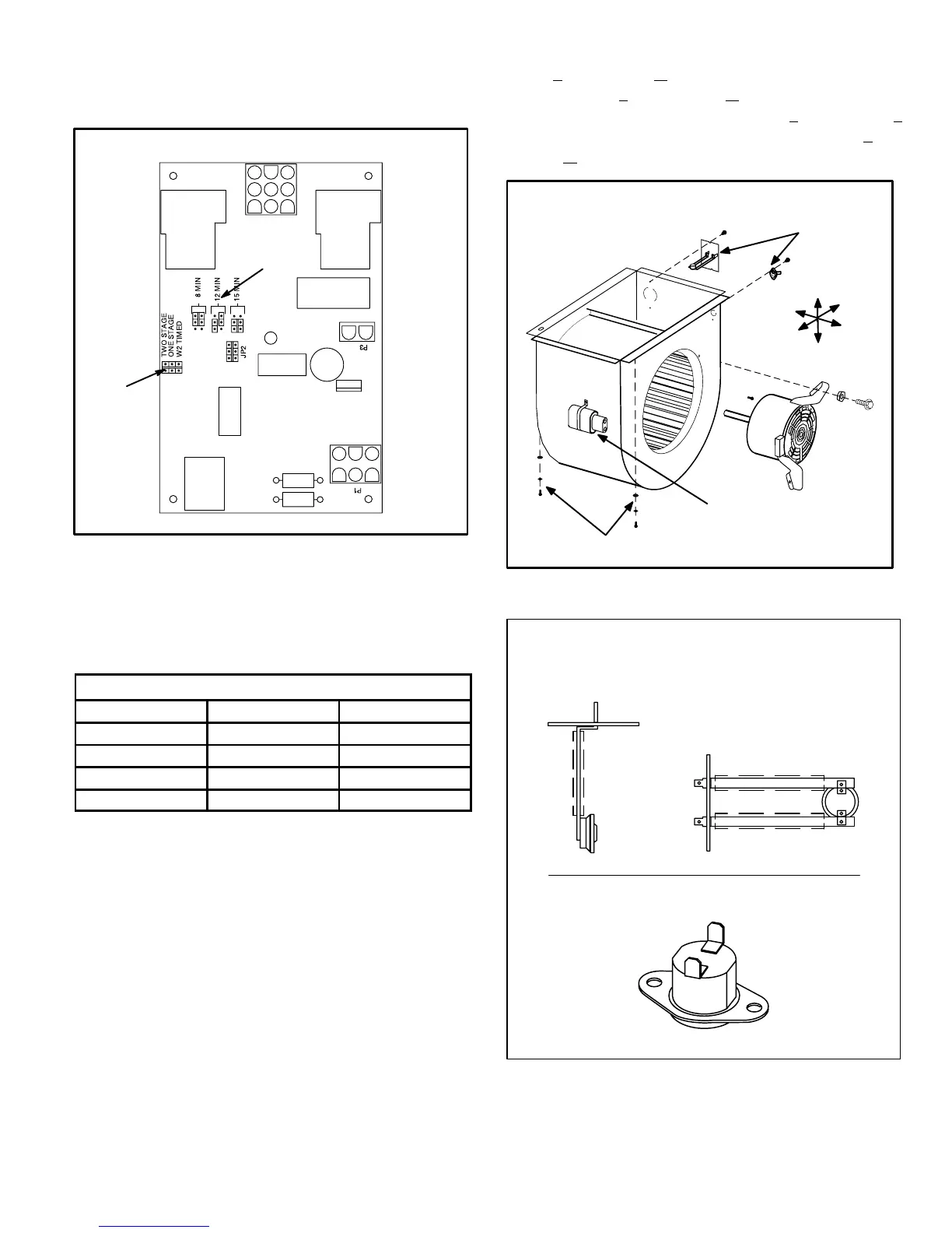
TWO–STAGE CONTROL BOARD
MODE OF
OPERATION
JUMPER
W2 TIMED ON
DELAY JUMPER
FIGURE 5
B–Blower Motor Assembly
All G27M units use direct drive blower motors. All mo-
tors used are 120V permanent split capacitor motors to
ensure maximum efficiency. See table 4 for ratings.
Table 4
G27M BLOWER RATINGS 120V
BLOWER MOTOR HP CAP
G27M2–60 1/4 5MF 370V
G27M3–75 1/3 5MF 370V
G27M4–100 1/2 7.5MF 370V
G27M5–120 3/4 40MF 370V
Secondary Limit Switches
[(1)S21 and (2)S21]
The secondary limit switches [(1)S21 and (2)S21] on
G27M units are located in the blower compartment on
the back side of the blower housing (see figure 6). When
excess heat is sensed in the blower compartment, the
limit will open. If the limit is tripped, the SureLight control
energizes the supply air blower and closes the gas valve.
The limit automatically resets when unit temperature
returns to normal. Two limits are supplied in each fur-
nace. Figure 7 shows both switches. Both switches are
N.C. SPST auto-reset switches which actuate on a tem-
perature rise. The switches are factory set and cannot be
adjusted. The (1)S21 limit shown on the top opens at
140_F +
5_F (60.0_C + 2.8_C) on a temperature rise and
closes at 110_F + 10_F (43.3_C + 5.6_C). The (2)S21 limit
shown on the bottom opens at 165_F + 5_F (73.9_C +
2.8_C) on a temperature rise and closes at 135_F + 8_F
(57.2_C + 4.4_C).
FIGURE 6
SUPPLY AIR BLOWER
AND SECONDARY LIMITS
Front
Bottom
Right
Left
Top
Back
BLOWER
MOTOR
To Remove Blower From Unit: Remove Bolts and
Wiring Jackplugs. Then Slide Out Front of Unit.
MOTOR
CAPACITOR
SECONDARY
LIMITS (S21)
INSULATING COVER (s)
FIGURE 7
SECONDARY LIMIT SWITCHES
FOR G27M SERIES UNITS
SPADE CONNECTORS
INSULATING COVER
LIMIT
LIMIT
(1)S21
(2)S21
 Loading...


