Page 28
Switches 11 and 12 −− Heating Mode Blower Speed −−
Switches 11 and 12 are used to select heating mode blower
motor speed. The unit is shipped from the factory with the
dip switches positioned for medium low (2) speed indoor
blower motor operation during the heating mode. The table
below provides the heating mode blower speeds that will
result from different switch settings. Refer to blower data
tables at the front of this manual for corresponding cfm val-
ues.
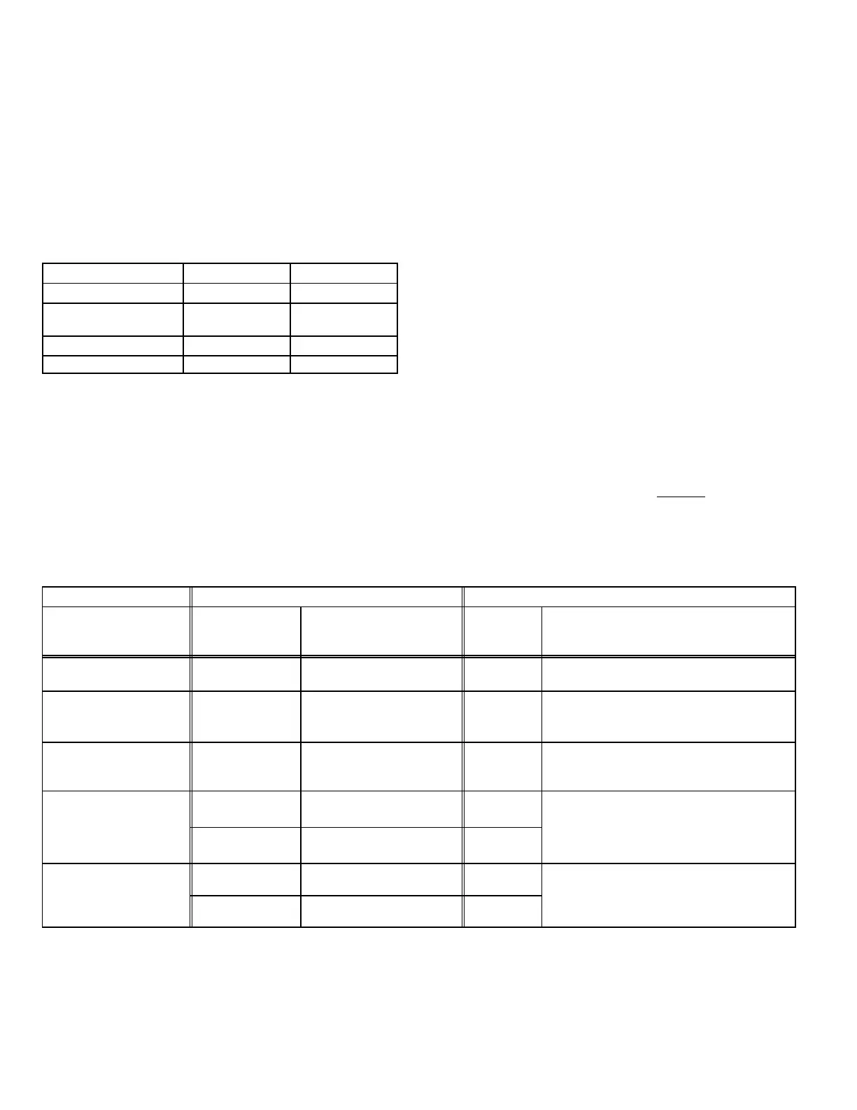
TABLE 26
Heating Mode Blower Speeds
Speed
Switch 11 Switch 12
1 − Low On On
2 − Medium Low
(Factory)
Off On
3 − Medium High On Off
4 − High Off Off
On−Board Jumper W914
On−board jumper W914, which connects terminals DS and
R on the integrated control board, must be cut when the fur-
nace is installed with either the Harmony II zone control
board or the CCB1 EfficiencyPlus humidity control. Refer to
table 27 for operation sequence in applications including a
G32V, CCB1 and single−speed outdoor unit. Table 28 gives
the operation sequence in applications with a two−speed
outdoor unit.
On−Board Jumper W951
On−board jumper W951, which connects terminals R and O
on the integrated control board, must be cut when the fur-
nace is installed in applications which include a heat pump
unit and the FM21 FuelMaster control board.
On−Board Jumper W915
On board jumper W915, which connects Y1 to Y2 terminals
on the integrated control board terminal strip must be cut if
two−stage cooling will be used.
On−Board Jumper W6
On board jumper W6 is an external measuring device for in-
door blower CFM. If by chance W6 is cut, the CFM LED will
not operate but the furnace will operate as normal. The
jumper has no affect on furnace operation.
Diagnostic LEDs (DS1 and DS2)
Two diagnostic LEDs are located on the two−stage, variable
speed integrated control just to the left of the first bank of dip
switches. These lights’ flashes correspond with diagnostic
codes detailed on in table 21.
Status LEDs (HEAT, HI/LO, ON/OFF and CFM)
The integrated control includes four LEDs which indicate
operating status. The green ON/OFF LED is lit any time the
blower is operating. The green CFM LED indicates the
blower motor speed. Count the number of blinks between
the two−second pauses to determine the CFM. Each blink
represents approximately 100 CFM. The yellow HI/LO LED
is lit when the W914 (DS to R) jumper has not
been clipped
for CCB1 or Harmony operation. The yellow HEAT LED is lit
when the indoor blower is operating at the HEATING
speed.
TABLE 27
G32V−5, CCB1 and Single−Speed Outdoor Unit
OPERATING MODE SYSTEM DEMAND SYSTEM RESPONSE
System Condition
Thermostat
Demand
*Relative Humidity
(EfficiencyPlus Lights)
Blower
CFM
(COOL)
Comments
Normal operation Y1
No demand. Humidity
level is acceptable
COOL
Compressor demand and indoor blower
speed controlled by thermostat demand.
*Call for humidity
removal during
cooling demand
Y1
Humidity level rises
above setpoint. Demand
initiated.
77%/74%
of COOL
Call for dehumidification initiated by CCB1
control. Indoor blower speed reduced by
CCB1 control.
Dehumidification
demand satisfied
during cooling demand.
Y1
Humidity level falls below
setpoint. No demand
COOL
When humidity demand is satisfied, blow-
er speed immediately increases to the
COOL CFM to hasten the end of the cycle.
Call for cooling after
None
Humidity level above set-
point. Demand initiated.
Off
Dehumidification mode begins when rela-
ca
or
um
y
removal.
Y1
Humidity level above set-
point. Demand initiated.
77%/74%
of COOL
tive humidity is greater than setpoint.
Humidity demand
satisfied between
None Over setpoint (1 or more) Off
While unit is not operating (no thermostat
demand) slide switch is moved down and
thermostat demands
(unit off cycle).
Y1 Change to acceptable COOL
eman
, s
e sw
c
s move
own an
back up. Blower operates at COOL CFM.
NOTE − When changing unit mode of operation from cooling to heating, indicating lights that are on will stay on until the first ther-
mostat heating demand.
* Reduced blower speed is 77% of COOL for V3 units and 74% of COOL for the V5 units.

 Loading...


