Page 41
7 − On field supplied terminations, a minimum separation
distance between the end of the exhaust pipe and the
end of the intake pipe is 8" (203mm).
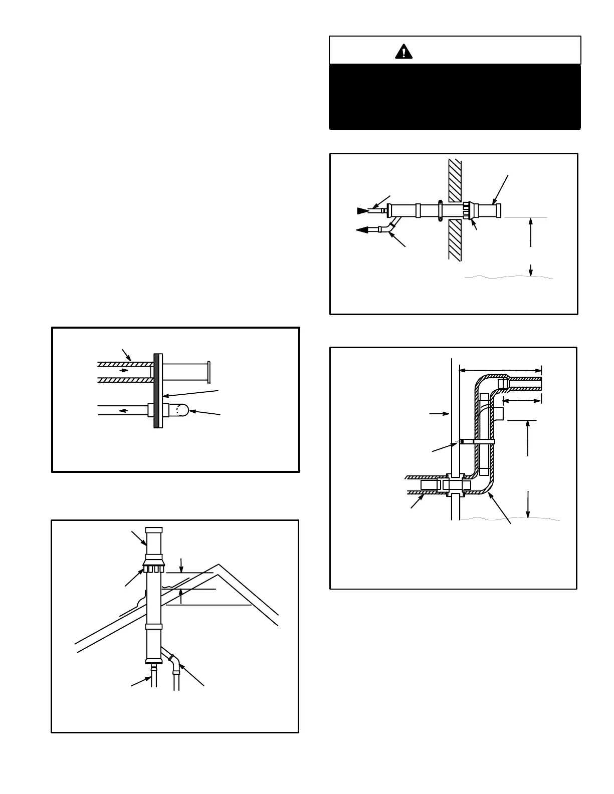
8 − If intake and exhaust piping must be run up a side wall
to position above snow accumulation or other obstruc-
tions, piping must be supported every 3 ft. (.91m) as
shown in figure 41. Refer to figures 39 and 40 for prop-
er piping method. WTK wall termination kit must be ex-
tended for use in this application. See figure 44 or use
kit WTKX shown in figure 45. When exhaust and intake
piping must be run up an outside wall, the exhaust pip-
ing is reduced to 1−1/2" (38mm) after the final elbow.
The intake piping may be equipped with a 90 elbow
turndown. Using turndown will add 5ft. (1.5m) to the
equivalent length of the pipe.
FIGURE 36
TOP VIEW
WALL TERMINATION
(22G44) LB−49107CD for 2 (50.8) Venting
(44J40) LB−65701A for 3 (76.2) Venting
Inches(mm)
OUTSIDE WALL
1/2 (12.7) FOAM INSULATION
IN UNCONDITIONED SPACE
Optional Turndown
Shown
(Intake Only)
FIGURE 37
12 (305) ABOVE
AVERAGE SNOW
ACCUMULATION
EXHAUST
EXHAUST
TERMINATION
INTAKE
TERMINATION
INTAKE
Inches (mm)
CONCENTRIC ROOFTOP TERMINATION
(60G77) LB−49107CE for G32V−75 Units Only
(33K97) LB−87942 for G32V−100 & −125 Units Only
IMPORTANT
For Canadian Installations Only:
In accordance to CAN/CGA−B149.1 and .2, the
minimum allowed distance between the combus-
tion air intake inlet and the exhaust outlet of other
appliances shall not be less than 12" (305mm).
FIGURE 38
EXHAUST
EXHAUST
TERMINATION
INTAKE
TERMINATION
INTAKE
12 (305) Min.
above grade.
CONCENTRIC WALL TERMINATION
(60G77) LB−49107CE for G32V−75 Units Only
(33K97) LB−87942 for G32V−100 & −125 Units Only
Inches
(mm)
FIGURE 39
12 (305) ABOVE
AVERAGE
SNOW
ACCUMULATION
UNCONDITIONED
SPACE
12 (305) MIN. for 2 (51)
20 (508) MAX. for 3 (76)
8 (203)
MIN.
1/2 (13) FOAM
INSULATION
1/2 (13) FOAM
INSULATION IN
UNCONDITIONED
SPACE
PROVIDE SUPPORT
FOR INTAKE AND
EXHAUST LINES EVERY
36 (914)
OUTSIDE WALL
Inches(mm)
SIDE VIEW
WALL RING TERMINATION
(15F74) LB−49107CB for 2" (51) Venting
9 − Position termination ends so they are free from any ob-
structions and above the level of snow accumulation
(where applicable). Termination ends must be a mini-
mum of 12" (305mm) above grade level. Do not point
into window wells, stairwells, alcoves, courtyard areas
or other recessed areas. Do not position termination
ends closer than 12" below roof eaves or above a walk-
way. Since the G32V is a certified direct vent, Category
IV gas furnace, the location of the termination is limited
by building codes. In the absence of local codes, refer to
the current National Fuel Gas Code ANSI Z223−1 in
U.S.A., and current standards CAN/CGA−B149.1 /.2 of

 Loading...


