Page 77
MATCH UP COMMENTS OR SEQUENCE
WIRING
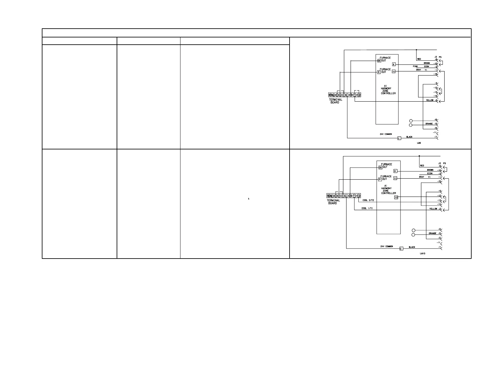
G32V−4 OPERATION SEQUENCE AND JUMPERS SUMMARY WITH VSP3 (COOLING CONTINUED)
Harmony and
Two-Speed Compressor
Y1 to Y2
and
O to R
(Remove
jumper from
Y1 to DS.)
Remove the wire from Pin #2 and
Pin #13 of the J49 harness connec-
tor at the motor and the wire from
Pin #3 of the J73 harness connec-
tor on the VSP control board.
Insulate the wire ends and secure
them to prevent shorting. Blower
operates on PWM signal generated
by the Harmony control board con-
trol board. The Harmony control
board overrides blower speed taps.
Blower speed varies according to
the zone’s demand.
(continued from previous page)
FOR HEATING JUMPERS
SEE SEE HEATING SECTION
ABOVE
T−STRIP JUMPER
O to R
(Remove jumper
from Y1 to DS
and Y1 to Y2.)
Remove the wire from Pin #2 and Pin
#13 of the J49 harness connector at
the motor and the wire from Pin #3 of
the J73 harness connector on the
VSP control board.
Insulate the wire ends and secure
them to prevent shorting. Blower op-
erates on PWM signal generated by
the Harmony control board.
The Harmony control board overrides
blower speed taps. Blower speed
varies according to zone’s demand.
CONNECTIONS
Harmony and
Single-Speed
Compressor

 Loading...


