G43UF / Page 8
FILTER AIR RESISTANCE
For 1 Inch (25 mm) Cleanable Filter (Field Provided)
cfm L/s in. w.g.
Pa
0
0 0.00 0
200 95 0.01 0
400 190 0.03
5
600
285 0.04 10
800 380 0.06 15
1000 470 0.09
20
1200
565 0.12 30
1400 660 0.15 35
1600 755 0.19
45
1800
850 0.23 55
2000 945 0.27 65
2200 1040 0.33
80
2400
1130 0.38 95
2600 1225 0.44 110
HIGH ALTITUDE INFORMATION
Pressure regulator adjustment may be required depending on
altitude. See below for proper pressure regulator setting.
Fuel Altitude − ft. (m)
Manifold Pressure
(Outlet)
in. w.g. (kPa)
Natural
0−4500 (0−1372) 3.5 (0.87)
4501−7500 (1373−2286)
2
3.5 (0.87)
7501−10000 (2287−3048)
1,2
3.5 (0.87)
3
LPG
0−4500 (0−1372) 10.0 (2.49)
Propane
4501−7500 (1373−2286)
2
10.0 (2.49)
7501−10,000 (0−3048)
2
10.0 (2.49)
1
High Altitude Orifice Kit required, see Gas Heat Accessories table for order number.
2
High Altitude Pressure Switch Kits as required, see Gas Heat Accessories table for
order number.
3
LPG/Propane conversion kit required, see Gas Heat Accessories table for order
number.
INSTALLATION CLEARANCES
Sides
1
0 inches (0 mm)
Rear 0 inches (0 mm)
Top/Plenum 1 inch (25 mm)
Front 0 inches (0 mm)
Front (service/alcove) 24 inches (610 mm)
Floor
2
Combustible
NOTE − Air for combustion and supply air ventilation must conform to the methods
outlined in American National Standard (ANSI-Z223.1) National Fuel Gas Code or
National Standard of Canada CAN/CGA-149.1, & CAN/CGA-149.2 Installation Code
for Gas Burning Appliances".
NOTE−In the U.S. flue sizing must conform to the methods outlined in current
GAMA/A.G.A. venting tables, American National Standard (ANSI-Z223.1) National
Fuel Gas Code or applicable provisions of local building codes. In Canada flue sizing
must conform to the methods outlined in National Standard of Canada
CAN/CGA-149.1 and .2.
1
Allow proper clearances to accommodate condensate trap and vent pipe installation.
2
Do not install the furnace directly on carpeting, tile, or other combustible materials other
than wood flooring.
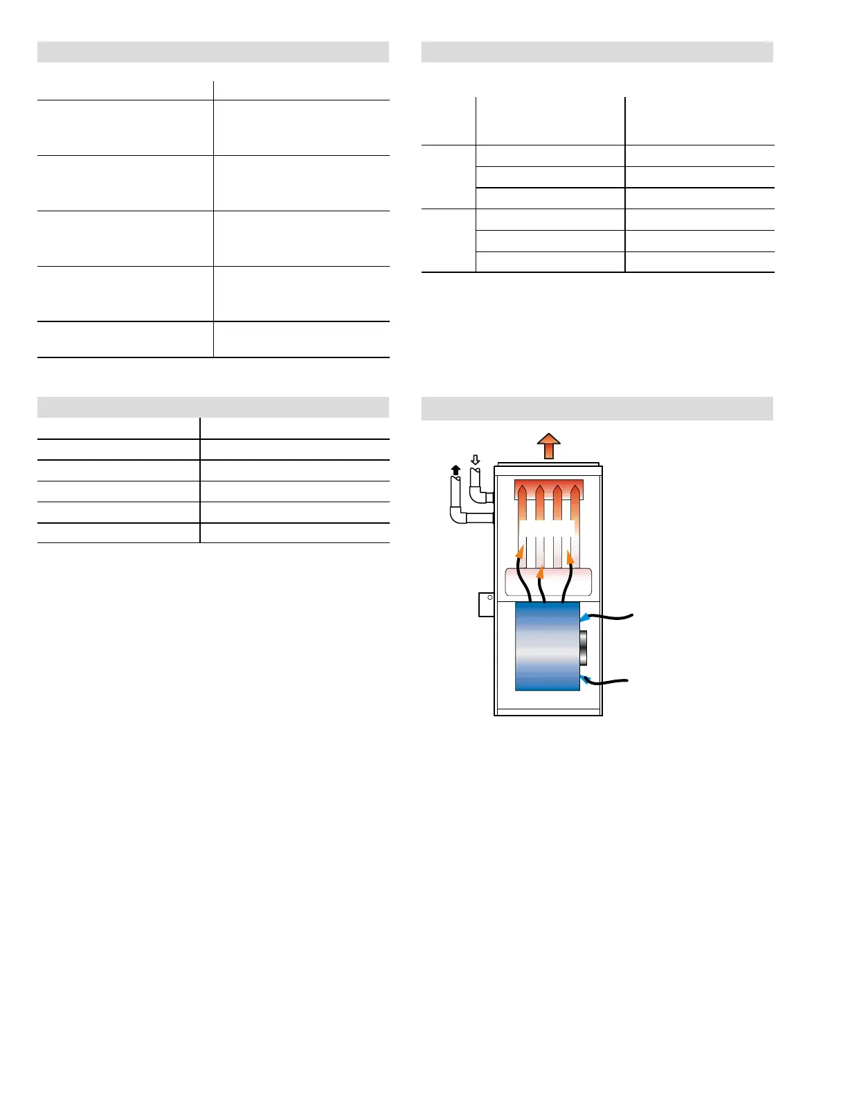
INSTALLATION CONFIGURATIONS
HEAT
EXCHANGER
BLOWER
CONDENSATE
DRAIN
VENT
PIPING
AIR FLOW
NOTE − The vent
piping and conden-
sate drain can be
moved to the other
side of the unit. Vent
piping and drain
must be installed on
the same side of the
unit with each other
unless optional Con-
densate Trap Alter-
nate Location Kit is
used.

 Loading...