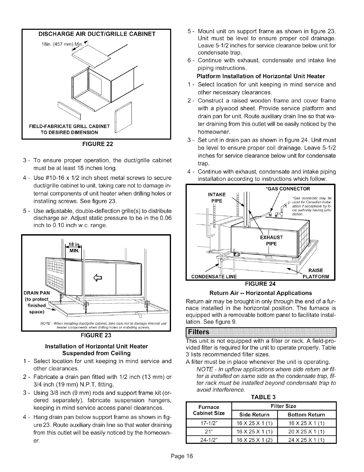
DISCHARGE AIR DUCT/GRILLE CABINET
18in. (457 mm) k ql
FIELD-FABRICATE GRILL CABINET
TO DESIRED DIMENSION
FIGURE 22
3- To ensure proper operation, the duct/grille cabinet
must be at least 18 inches long.
4 - Use #10-16 x 1/2 inch sheet metal screws to secure
duct/grille cabinet to unit, taking care not to damage in-
ternal components of unit heater when drilling holes or
installing screws, See figure 23,
5 - Use adjustable, double-deflection grille(s) to distribute
discharge air, Adjust static pressure to be in the 0,06
inch to 0,10 inch w,c, range,
NOTE - Wtlen installing duct/grille cabinet, take care not to damage internal unit
beater components when drilling holes or instalhng screws.
FIGURE 23
Installation of Horizontal Unit Heater
Suspended from Ceiling
1 - Select location for unit keeping in mind service and
other clearances.
2 - Fabricate a drain pan fitted with 1/2 inch (13 mm) or
3/4 inch (19 mm) N.P.T. fitting.
3 - Using 3/8 inch (9 mm) rods and support frame kit (or-
dered separately), fabricate suspension hangers,
keeping in mind service access panel clearances.
4 - Hang drain pan below support frame as shown in fig-
ure 23, Route auxiliary drain line so that water draining
from this outlet will be easily noticed by the homeown-
er,
5 - Mount unit on support frame as shown in figure 23.
Unit must be level to ensure proper coil drainage,
Leave 5-1/2 inches for service clearance below unit for
condensate trap.
6- Continue with exhaust, condensate and intake line
piping instructions,
Platform Installation of Horizontal Unit Heater
1 - Select location for unit keeping in mind service and
other necessary clearances.
2 - Construct a raised wooden frame and cover frame
with a plywood sheet. Provide service platform and
drain pan for unit. Route auxiliary drain line so that wa-
ter draining from this outlet will be easily noticed by the
homeowner,
3 - Set unit in drain pan as shown in figure 24, Unit must
be level to ensure proper coil drainage, Leave 5-1/2
inches for service clearance below unit for condensate
trap.
4 - Continue with exhaust, condensate and intake piping
installation according to instructions which follow,
*GAS CONNECTOR
INTAKE
*Gas connector may be
PIPE used for Canadian instal-
lation if acceptable by lo-
cal authority havmg juds-
diction.
RAISE
CONDENSATE LINE PLATFORM
FIGURE 24
Return Air -- Horizontal Applications
Return air may be brought in only through the end of a fur-
nace installed in the horizontal position. The furnace is
equipped with a removable bottom panel to facilitate instal-
lation. See figure 9,
This unit is not equipped with a filter or rack, A field-pro-
vided filter is required for the unit to operate properly. Table
3 lists recommended filter sizes.
A filter must be in place whenever the unit is operating.
NOTE - In upflow applications where side return air fil-
ter is installed on same side as the condensate trap, fil-
ter rack must be installed beyond condensate trap to
avoid interference,
TABLE 3
Furnace
Cabinet Size
17-1/2"
21"
24-1/2"
Filter Size
Side Return Bottom Return
16X25X 1(1) 16X25Xl(1)
16X25X 1(1) 20X25Xl(1)
16X25X 1(2) 24X25X 1(1)
Page 16
 Loading...


