4 - Testfitjointandmarkdepthoffittingonoutsideof
pipe,
5- UniformlyapplyliberalcoatofPVCprimerforPVCor
ABScleanerforABStoinsidesocketsurfaceoffitting
andmaleendofpipetodepthoffittingsocket,
6 - Promptlyapplysolventcementtoendofpipeandin-
sidesocketsurfaceoffitting.Cementshouldbeap-
pliedlightlybutuniformlytoinsideofsocket,Takecare
tokeepexcesscementoutofsocket,Applysecond
coattoendofpipe.
NOTE - Time is critical at this stage. Do not allow prim-
er to dry before applying cement.
7 - Immediately after applying last coat of cement to pipe,
and while both inside socket surface and end of pipe
are wet with cement, forcefully insert end of pipe into
socket until it bottoms out, Turn PVC pipe 1/4 turn dur-
ing assembly (but not after pipe is fully inserted) to dis-
tribute cement evenly, DO NOT turn ABS or cellular
core pipe,
NOTE - Assembly should be completed within 20 sec-
onds after last application of cement. Hammer blows
should not be used when inserting pipe.
8 - After assembly, wipe excess cement from pipe at end
of fitting socket. A properly made joint will show a bead
around its entire perimeter, Any gaps may indicate a
defective assembly due to insufficient solvent,
9 - Handle joints carefully until completely set,
4 - Isolate piping at the point where it exits the outside wall
or roof in order to prevent transmission of vibration to
the structure,
5 - When furnace is installed in a residence where unit is
shut down for an extended period of time, such as a
vacation home, make provisions for draining conden-
sate collection trap and lines,
Exhaust Piping (Figures 27 and 28)
NOTE - A 2" diameter street ell is located on the blower
deck of 60C-110 and -111 units. Street ell must be_glued
with ABS solvent cement directly into the unit flue collar.
See figure 27. A 3"to 2" reducing ell is located on the blower
deck of the 60D-135 units. In upflow or downflow ap-
plications, the reducing eft must be glued with ABS sol-
vent cement directly into the unit flue collar.
1 - Choose the appropriate side for venting in upfiow or
downfiow positions, Exhaust piping exits from the top
of the unit in horizontal air discharge applications.
Glue the field-provided exhaust vent pipe (or provided
street ell or reducing ell in upflow or downflow applica-
tions) to the flue collar, All PVC cement joints should
be made according to the specifications outlined in
ASTM D 2855. Refer to pipe and fittings specifications
and gluing procedures,
IMPORTANT
The thickness of construction through which vent pipes
may be installed is 24" (610mm) maximum and 3/4"
(19mm) minimum. If a G61MPV furnace replaces a furnace
which was commonly vented with another gas appliance,
the size of the existing vent pipe for that gas appliance must
be checked. Without the heat of the original furnace flue
products, the existing vent pipe is probably oversized for
the single water heater or other appliance. The vent should
be checked for proper draw with the remaining appliance.
1 - Use recommended piping materials for exhaust pip-
ing.
2 - Secure all joints so that they are gas-tight using ap-
proved cement.
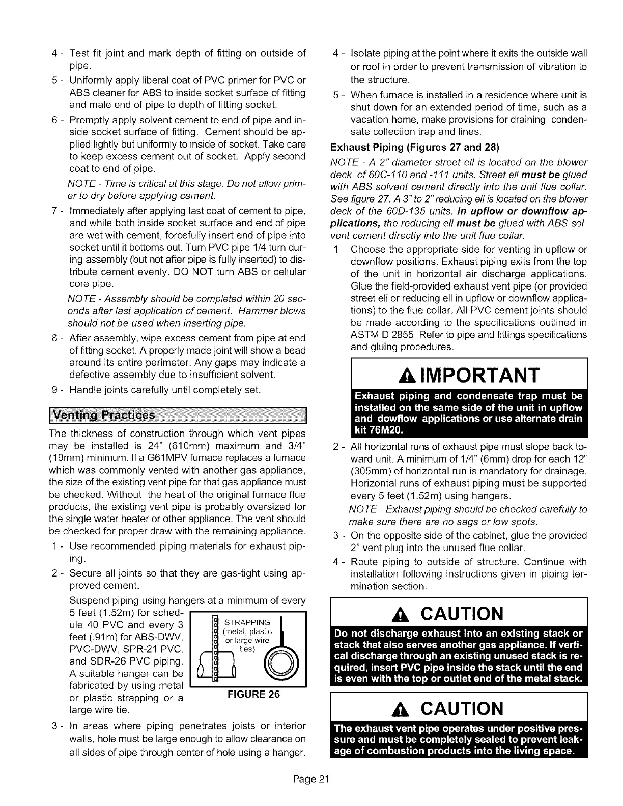
Suspend piping using hangers at a minimum of every
5 feet (1.52m) for sched-
ule 40 PVC and every 3
feet (.91m) for ABS-DWV,
PVC-DWV, SPR-21 PVC,
and SDR-26 PVC piping,
A suitable hanger can be
fabricated by using metal
or plastic strapping or a
large wire tie.
STRAPPING I
(metal, plastic II
la[gewire 1
ttes) 0
FIGURE 26
3- In areas where piping penetrates joists or interior
walls, hole must be large enough to allow clearance on
all sides of pipe through center of hole using a hanger.
2 - All horizontal runs of exhaust pipe must slope back to-
ward unit. A minimum of 1/4" (6mm) drop for each 12"
(305mm) of horizontal run is mandatory for drainage.
Horizontal runs of exhaust piping must be supported
every 5 feet (1,52m) using hangers.
NOTE - Exhaust piping should be checked carefully to
make sure there are no sags or low spots.
3 - On the opposite side of the cabinet, glue the provided
2" vent plug into the unused flue collar,
4- Route piping to outside of structure, Continue with
installation following instructions given in piping ter-
mination section,
CAUTION
Ak CAUTION
Page 21
 Loading...


