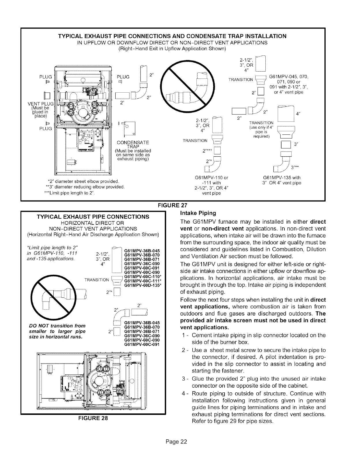
PLUG
VENT PLUG
(Must be
glued in
place)
PLUG
TYPICAL EXHAUST PIPE CONNECTIONS AND CONDENSATE TRAP INSTALLATION
IN UPFLOW OR DOWNFLOW DIRECT OR NON-DIRECT VENT APPLICATIONS
(Right-Hand Exit in Upflow Application Shown)
°_ D -°° !
D
t CONDENSATE
TRAP
(Must be installed
on same side as
exhaust piping)
3", OR
4"
2-1/2",
3", OR
4"
_ G61MPV-045, 070,
TRANSITION 071, 090 or
n 091 with 2-112", 3",
II
2" or 4" vent pipe
2" _4"
TRANSITION
(use only if4"
pipe is
required)
[_3"
"2" diameter street elbow provided.
**3" diameter reducing elbow provided.
***Limit pipe length to 2".
G61MPV- 110 or G61MPV-135 with
-111 with 3" OR 4" vent pipe
2-1/2", 3", OR 4"
vent pipe
FIGURE
TYPICAL EXHAUST PIPE CONNECTIONS
HORIZONTAL DIRECT OR
NON-DIRECT VENT APPLICATIONS
(Horizontal Right-Hand Air Discharge Application Shown)
*Limit pipe length to 2"
in G61MPV-110, -111
and - 135 applications.
c_] G61MPV-36B-045
2-1/2", G61MPV-36B-070
3", OR G61MPV-36B-071
4" G61MPV-36C-090
G61MPV-60C-091
G61MPV-60C-090
DO NOT transition from
smaller to larger pipe
size in horizontal runs.
G61MPV-36B-070
2"_ G61MPV-36B-071
G61MPV-36C-090
G61MPV-60C-090
G61MPV-60C-091
FIGURE 28
27
Intake Piping
The G61MPV furnace may be installed in either direct
vent or non-direct vent applications. In non-direct vent
applications, when intake air will be drawn into the furnace
from the surrounding space, the indoor air quality must be
considered and guidelines listed in Combustion, Dilution
and Ventilation Air section must be followed.
The G61MPV unit is designed for either left-side or right-
side air intake connections in either upflow or downflow ap-
plications. In horizontal applications, air intake must be
brought in through the top. Intake air piping is independent
of exhaust piping.
Follow the next four steps when installing the unit in direct
vent applications, where combustion air is taken from
outdoors and flue gases are discharged outdoors. The
provided air intake screen must not be used in direct
vent applications.
1 - Cement intake piping in slip connector located on the
side of the burner box.
2 - Use a sheet metal screw to secure the intake pipe to
the connector, if desired. A pilot indentation is pro-
vided in the slip connector to assist in locating and
starting the fastener.
3- Glue the provided 2" plug into the unused air intake
connector on the opposite side of the cabinet.
4- Route piping to outside of structure. Continue with
installation following instructions given in general
guide lines for piping terminations and in intake and
exhaust piping terminations for direct vent sections.
Refer to figure 29 for pipe sizes.
Page 22
 Loading...


