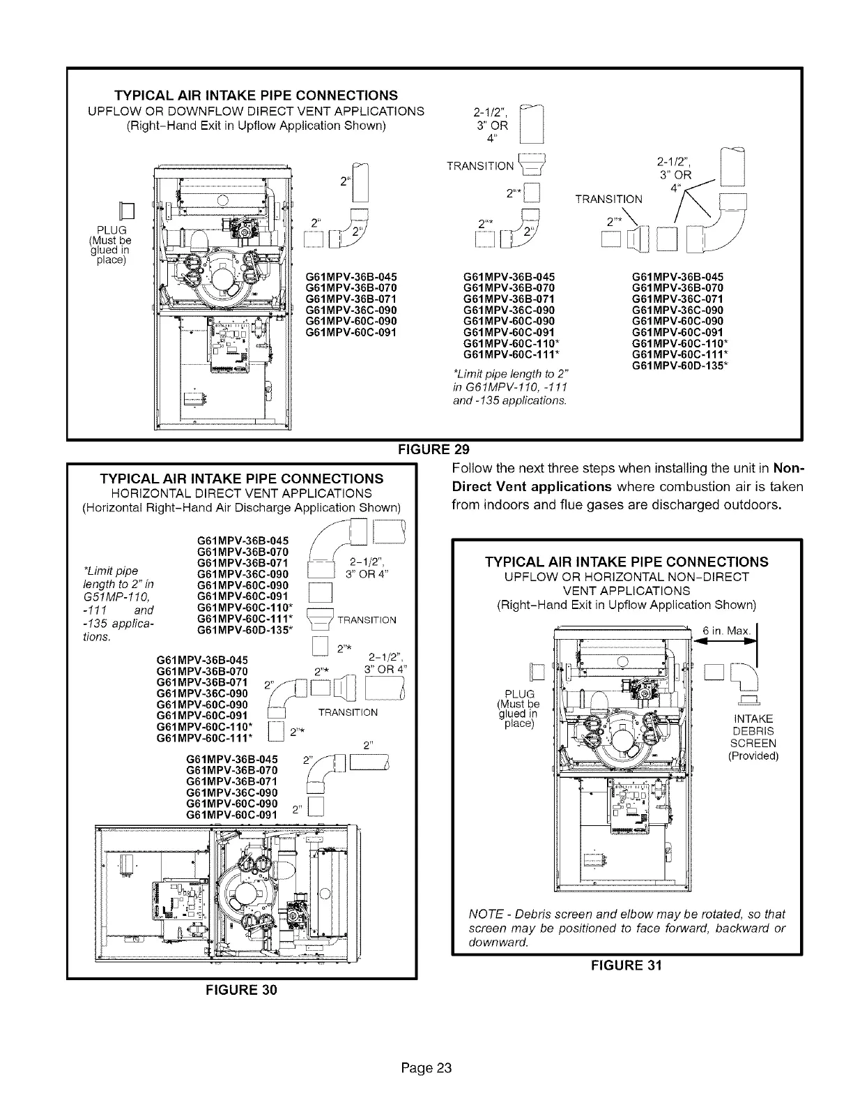
TYPICAL AIR INTAKE PIPE CONNECTIONS
UPFLOW OR DOWNFLOW DIRECT VENT APPLICATIONS
(Right-Hand Exit in Upflow Application Shown)
PLUG
(Must be
glued in
place)
_' 2'_
2"_
E3
G61MPV-36B-045
G61MPV-36B-070
G61MPV-36B-071
G61MPV-36C-090
I_ G61MPV-60C-090
G61MPV-60C-091
2-1/2", [_
3" OR
4'
TRANSITIONLL /
2"*_
2"* _ 2_
E3
G61 MPV-36B-045
G61 MPV-36B-070
G61 MPV-36B-071
G61 MPV-36C-090
G61 MPV-60C-090
G61 MPV-60C-091
G61MPV-60C-110*
G61MPV-60C-111*
*Limit pipe length to 2"
in G61MPV-110, -111
and -135 applications.
TRANSITION
2-1/2", [_3" OR
4'
G61 MPV-36B-045
G61 MPV-36B-070
G61 MPV-36C-071
G61 MPV-36C-090
G61 MPV-60C-090
G61 MPV-60C-091
G61 MPV-60C-110*
G61MPV-60C-111*
G61 MPV-60D-135*
FIGURE 29
Follow the next three steps when installing the unit in Non-
TYPICAL AIR INTAKE PIPE CONNECTIONS
HORIZONTAL DIRECT VENT APPLICATIONS
(Horizontal Right-Hand Air Discharge Application Shown)
=J
*Limit pipe
length to 2" in
G51MP-110,
-111 and
-135 applica-
tions.
G61MPV-36B-045
G61MPV-36B-070
G61MPV-36B-071
G61MPV-36C-090
G61MPV-60C-090
G61MPV-60C-091
G61MPV-60C-110*
G61MPV-60C-111* TRANSITION
G61MPV-60D-135*
2. _
G61 MPV-36B-045 2-1/2",
G61MPV-36B-070 2"* 3" OR 4"
G61 MPV-36B-071
G61 MPV-36C-090
G61 MPV-60C-090
G61 MPV-60C-091
G61MPV-60C-110* _ 2"*
G61MPV-60C-111*
2"
G61MPV-36B-045
G61MPV-36B-070
G61MPV-36B-071
G61MPV-36C-090
G61MPV-60C-090
G61MPV-60C-091 2"
Direct Vent applications where combustion air is taken
from indoors and flue gases are discharged outdoors.
TYPICAL AIR INTAKE PIPE CONNECTIONS
UPFLOW OR HORIZONTAL NON-DIRECT
VENT APPLICATIONS
(Right-Hand Exit in Upf!ow Application Shown)
PLUG
(Must be Fq
glued in
place) INTAKE
DEBRIS
SCREEN
(Provided)
NOTE - Debris screen and elbow may be rotated, so that
screen may be positioned to face forward, backward or
downward.
FIGURE 31
FIGURE 30
Page 23
 Loading...


