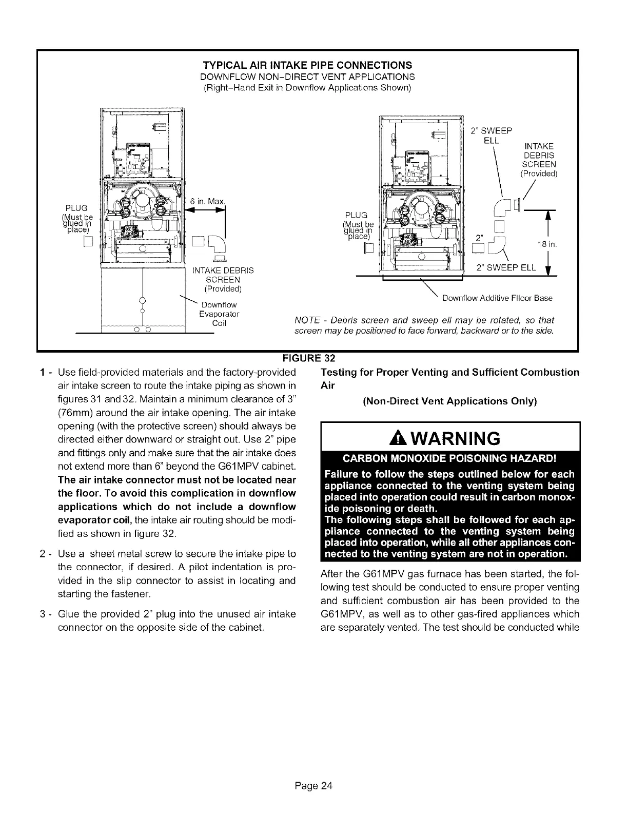
TYPICAL AIR INTAKE PIPE CONNECTIONS
DOWNFLOW NON-DIRECT VENT APPLICATIONS
(Right-Hand Exit in Downflow Applications Shown)
PLUG
_lpqUst,be
ea in
lace)
0 0
6 in. Max,
r_
INTAKE DEBRIS
SCREEN
(Provided)
Downflow
Evaporator
Coil
PLUG
(g_ust,be
ea I
_L_ace_
I
I
2" SWEEP
ELL
INTAKE
DEBRIS
SCREEN
(Provided)
/
f
[_ 181n.|
2" SWEEP ELL
T
i
_\ Downflow Additive FIIoor Base
NOTE - Debris screen and sweep ell may be rotated, so that
screen may be positioned to face forward, backward or to the side.
FIGURE 32
1 - Use field-provided materials and the factory-provided
air intake screen to route the intake piping as shown in
figures 31 and 32, Maintain a minimum clearance of 3"
(76mm) around the air intake opening. The air intake
opening (with the protective screen) should always be
directed either downward or straight out, Use 2" pipe
and fittings only and make sure that the air intake does
not extend more than 6" beyond the G61MPV cabinet,
The air intake connector must not be located near
the floor. To avoid this complication in downflow
applications which do not include a downflow
evaporator coil, the intake air routing should be modi-
fied as shown in figure 32,
Testing for Proper Venting and Sufficient Combustion
Air
(Non-Direct Vent Applications Only)
WARNING
2 - Use a sheet metal screw to secure the intake pipe to
the connector, if desired, A pilot indentation is pro-
vided in the slip connector to assist in locating and
starting the fastener,
3 - Glue the provided 2" plug into the unused air intake
connector on the opposite side of the cabinet,
After the G61MPV gas furnace has been started, the fol-
lowing test should be conducted to ensure proper venting
and sufficient combustion air has been provided to the
G61MPV, as well as to other gas-fired appliances which
are separately vented, The test should be conducted while
Page 24
 Loading...


