3- Ifexhaustpipingmustberunupasidewalltoposition
abovesnowaccumulationorotherobstructions,pip-
ingmustbesupportedevery3feet(.9m)asshownin
figure26,Refertofigure45forproperpipingmethod.
Whenexhaustpipingmustberunupanoutsidewall,
anyreductioninexhaustpipesizemustbedoneafter
thefinalelbow.
Inches(ram) 12" (305) Max. for 2" (51)
Unless Supported m
UNCONDITIONED
SPACE
OUTSIDE WALL
PROVIDE SUPPORT
FOR EXHAUST LINES
EVERY 30" (914)
FIELD-PROVIDED
REDUCER MAY BE
REQUIRED TO
ADAPT LARGER
VENT PiPE SIZE TO
TERMINATION
SIZE TER-
MINATION
PIPE PER
TABLE 8.
12" (305) ABOVE
AVERAGE SNOW
ACCUMULATION
1/2" (13) FOAM
INSULATION IN
UNCONDITIONED 112" (13) FOAM
SPACE INSULATION
SIDE VIEW
NON-DIRECT VENT WALL RING TERMINATION
(15F74)
FIGURE 45
G61MPV NON-DIRECT VENT APPLICATION
USING EXISTING CHIMNEY
SIZE TERMINATION
PIPE PER TABLE 8.
38
(76m_
203mm)
MINIMU 12"
(_5mm)ABOVE
AVERAGE:NOW
ACCUMULATION
SHEET
METALTOP
PLATE
/_SOLAT_
TOFORM
SEAL
STRAIGHT-CUT OR
' ANGLE CUT iN DIRECTION
OF ROOF SLOPE
EXHAUST VENT
1/2" (13ram)
WEATHERPROOF
INSULATION
SHOULDER OF FI_INGS
PROVIDE SUPPORT
OF PIPE ON TOP PLATE
3 8
(76ram
203rnm)
EXTERIOR
PORTION OF
CHIMNEY
NOTE - Do not discharge exhaust gases directly into any chimney or vent stack. If ver-
tical discharge through an existing unused chimney or stack is required, insert piping
inside chimney until the pipe open end is above top of chimney and terminate as illus-
trated. In any exterior portion of chimney, the exhaust vent must be insulated.
FIGURE 46
Condensate Piping
This unit is designed for either right- or left-side exit of con-
densate piping in either upflow or downflow applications;
however, it must be installed on the same side of the unit as
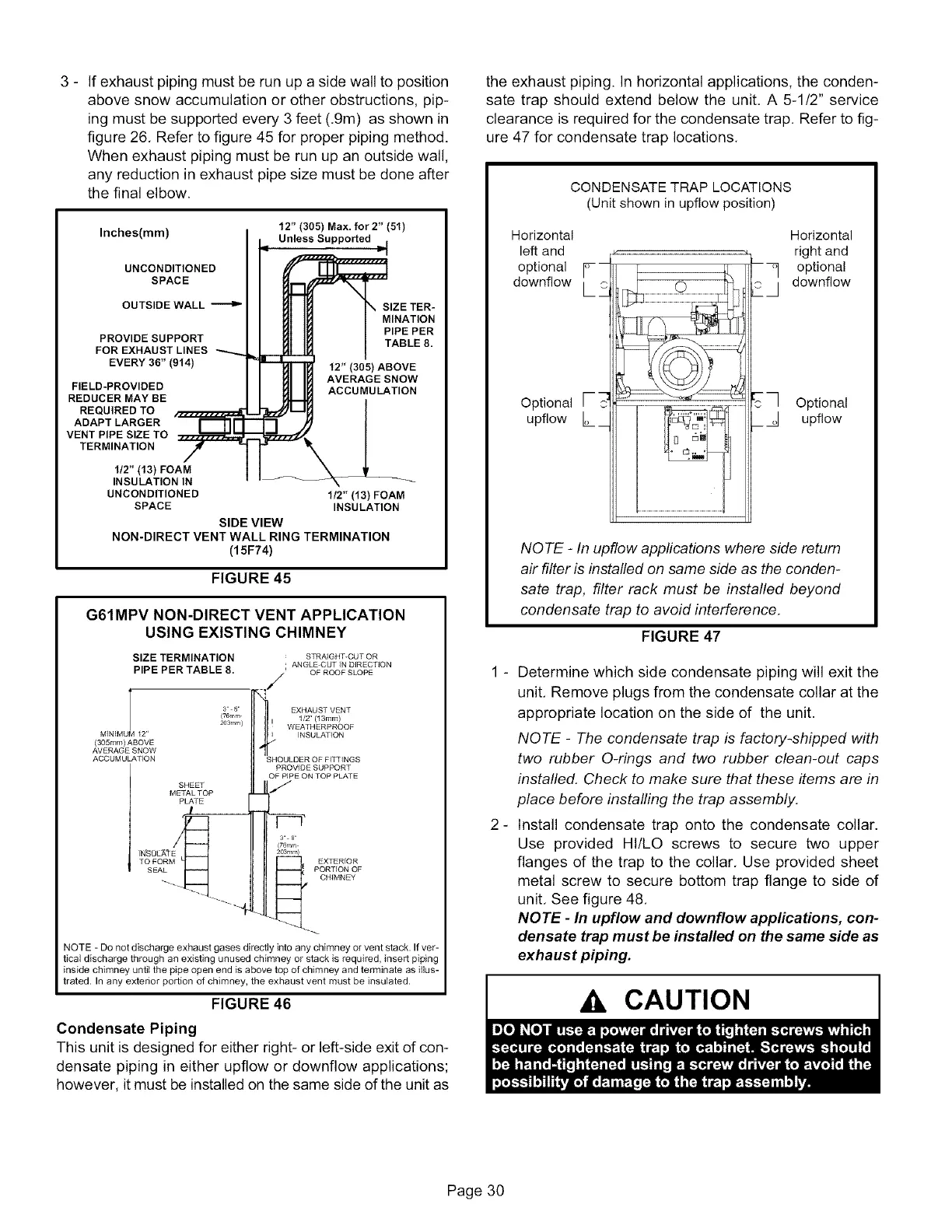
the exhaust piping. In horizontal applications, the conden-
sate trap should extend below the unit, A 5-1/2" service
clearance is required for the condensate trap, Refer to fig-
ure 47 for condensate trap locations,
CONDENSATE TRAP LOCATIONS
(Unit shown in upfiow position)
Horizontal Horizontal
left and .............................................................................................right and
downflow°pti°nal_--- _ --_ downflow°pti°nal
L--, :::::::::::::::::::::::::::::::::::::::::::::::.............!J
Optional [--
upflow L_
NOTE - In upflow applications where side return
air filter is installed on same side as the conden-
sate trap, filter rack must be installed beyond
condensate trap to avoid interference.
FIGURE 47
1 - Determine which side condensate piping will exit the
unit, Remove plugs from the condensate collar at the
appropriate location on the side of the unit.
NOTE - The condensate trap is factory-shipped with
two rubber Q-rings and two rubber clean-out caps
installed. Check to make sure that these items are in
place before installing the trap assembly.
2- Install condensate trap onto the condensate collar.
Use provided HI/LO screws to secure two upper
flanges of the trap to the collar, Use provided sheet
metal screw to secure bottom trap flange to side of
unit, See figure 48,
NOTE - In upflow and downflow applications, con-
densate trap must be installed on the same side as
exhaust piping.
CAUTION
Page 30
 Loading...


