&WARNING
Select a location that allows for the required clearances
that are listed on the unit nameplate. Also consider gas
supply connections, electrical supply, vent connection,
condensate trap and drain connections, and installation
and service clearances [24 inches (610 mm) at unit front].
The unit must be level from front to back and side to side.
NOTE - G61MPV-36B and -36C units with 1/2 hp blower
motors are equipped with three flexible legs and one rigid
leg. The rigid leg is equipped with a shipping bolt and a flat
white plastic washer (rather than the rubber mounting
grommet used with a flexible mounting leg). The bolt and
washer must be removed before the furnace is placed
into operation. After the bolt and washer have been re-
moved, the rigid leg will not touch the blower housing.
NQ TE - G61MPV-60D-135 units are equipped with a ship-
ping pad under the blower housing. Remove the shipping
pad prior to operation.
Allow for clearances to combustible materials as indicated
on the unit nameplate. Minimum clearances for closet or al-
cove installations are shown in figures 7, 12 and 16.
WARNING
WARN ING
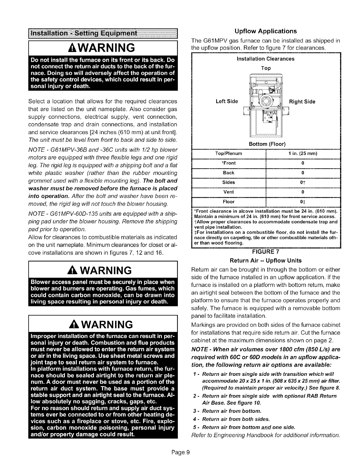
Upflow Applications
The G61MPV gas furnace can be installed as shipped in
the upflow position. Refer to figure 7 for clearances.
Installation Clearances
Top
Left Side
Right Side
;q
Bottom (Floor)
............................................... T...............................................
Top/Plenum i 1 in. (25 ram)
*Front I O
."................... ..................................................................
Sides i 01-
t
Vent i O
............................................... _ ................................................
Floor i O:_
| ............................................... _............................................... ._
*Front clearance in alcove installation must be 24 in. (610 ram).
Maintain a minimum of 24 in. (610 ram) for front service access.
TAllow proper clearances to accommodate condensate trap and
vent pipe installation.
| :_For installations on a combustible floor, do not install the fur-
i nace directly on carpeting, tile or other combustible materials oth-
i er than wood flooring.
=================================================================================================
FIGURE 7
Return Air -- Upflow Units
Return air can be brought in through the bottom or either
side of the furnace installed in an upfiow application. If the
furnace is installed on a platform with bottom return, make
an airtight seal between the bottom of the furnace and the
platform to ensure that the furnace operates properly and
safely. The furnace is equipped with a removable bottom
panel to facilitate installation.
Markings are provided on both sides of the furnace cabinet
for installations that require side return air. Cut the furnace
cabinet at the maximum dimensions shown on page 2.
NOTE - When air volumes over 1800 cfm (850 L/s) are
required with 60C or 60D models in an upflow applica-
tion, the following return air options are available:
1 - Return air from single side with transfion which will
accommodate 20 x 25 x I in. (508 x 635 x 25 mm) air filter.
(Required to maintain proper air velocity.) See figure 8.
2 - Return air from single side with optional RAB Return
Air Base. See figure 10.
3 - Return air from bottom.
4 - Return air from both sides.
5 - Return air from bottom and one side.
Refer to Engineering Handbook for additional information.
Page 9
 Loading...


